2023/12/01 update
Page Contents
AA Front Fenders TOC
*************Tap/Click*************
AA Rear Fenders TOC
*************Tap/Click*************
AA Running Boards+Shields TOC
*************Tap/Click*************
Front Fenders+Fender-Shields+Brackets
Front fender styles are shown in the images below. These were the two front fender styles used for AA production. Both styles had more than one design. The 12/27—6/30 fenders were fastened to one-piece AA running board shields (short or long). The 6/30—12/32 fenders included fender-shields which were fastened to separate AA running board shields (short or long).
Only 1931 AA wheel-welled fenders (i.e. fenders used with a right or left AA fender wheel carrier) were AA-chassis fenders. All other front fenders were A-chassis fenders.
Note that the RGJS (Areas 4 and 13) has details for fenders, fender-shields, and brackets as applied to the A-chassis.
12/27—6/30 Front Fenders+Brackets
For this date range, AA’s were fit with the A-chassis A-16005/06 RH/LH front fenders and A-16025 brackets. These parts had a number of design changes as follows. Additional changes are found in Area 13 of the RGJS.
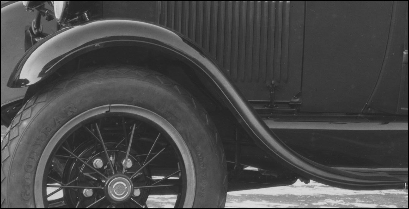
Designs d1—d4 (Front Fender) -These fenders are defined as having four designs for purposes of this documentation.
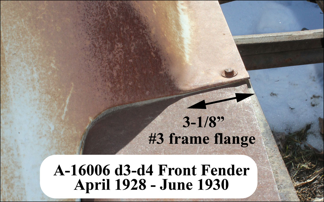
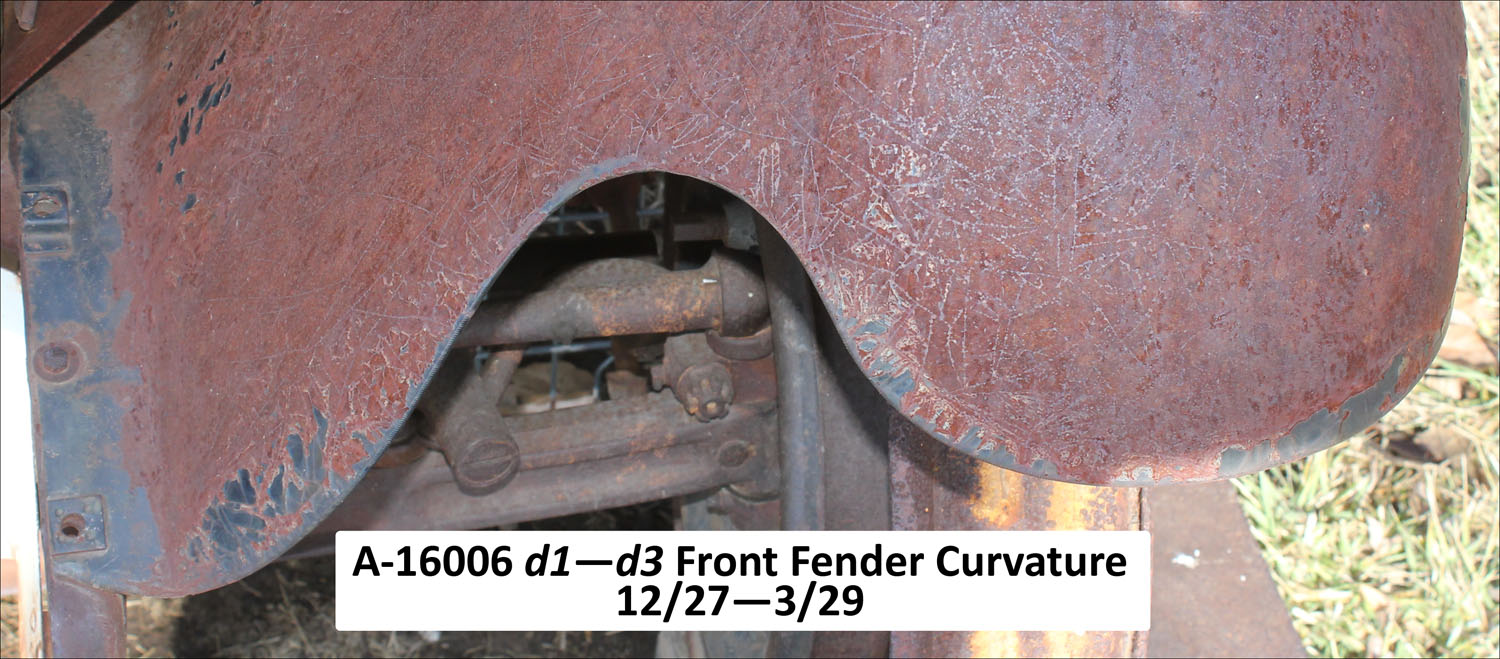
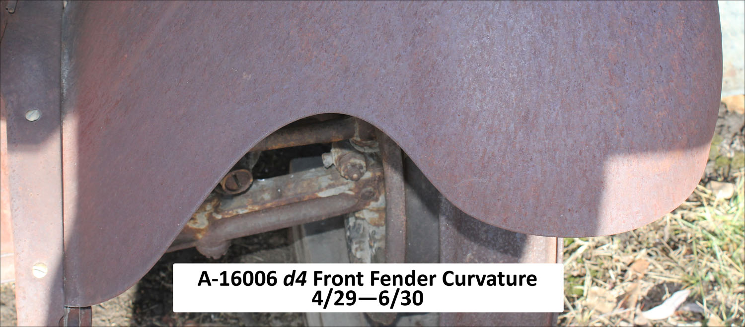
d1—d3 had different width over-the-frame flanges (i.e. the flange which was sandwiched between the frame and the hood shelf). d4 had a different front curvature.
See the 12/27—6/30 gallery for examples of d1—d4.
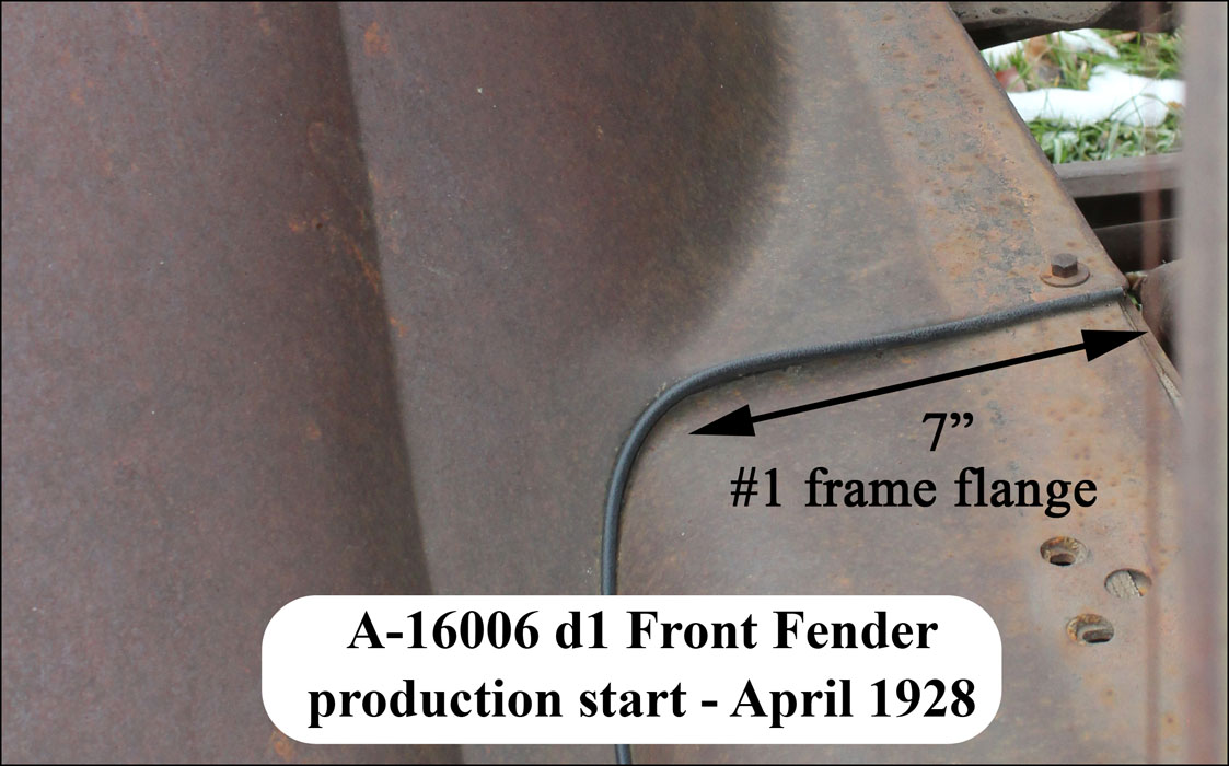
- d1 – 1927—4/28. These fenders had an over-the-frame flange which was approximately 7″ wide at the rear.
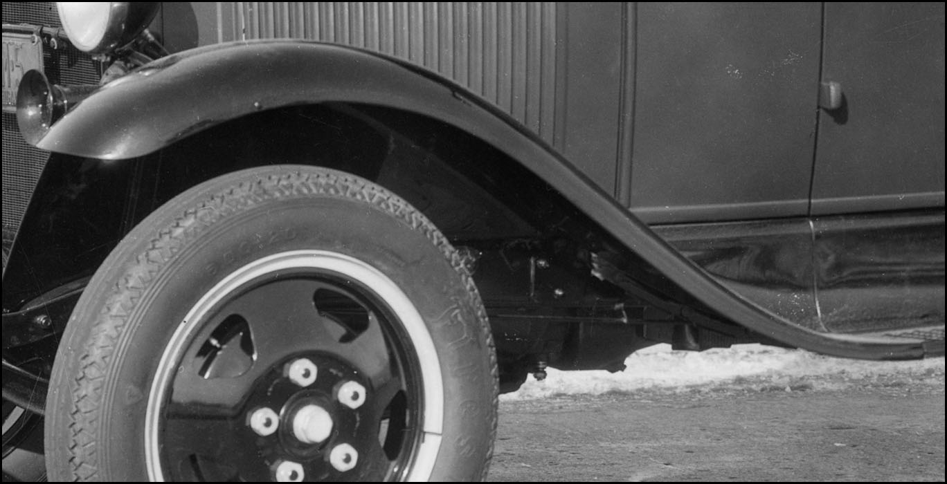
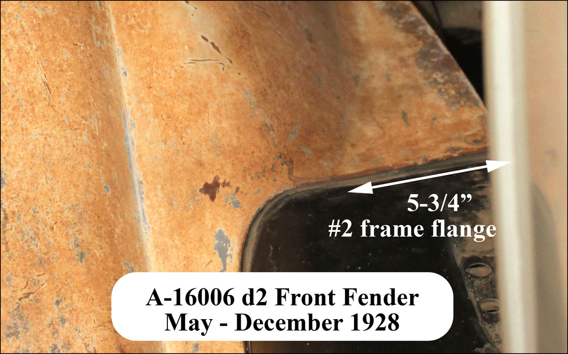
- d2 – May—June 1928 (with some used through 12/28). The over-the-frame flange was changed to be approximately 5-3/4″ wide at the rear.
- d3 – 7/28—5/29. The over-the-frame flange was changed to be approximately 3-1/8″ wide at the rear (note the overlap with d2 dates). Through 12/28, the d2 and d3 fenders were sometimes installed on opposite sides of the same AA.
- d4 – 4/29—6/30. The curvature at the front of the fender was changed to a less pronounced curve. The over-the-frame flange remained approximately 3-1/8″ wide at the rear.
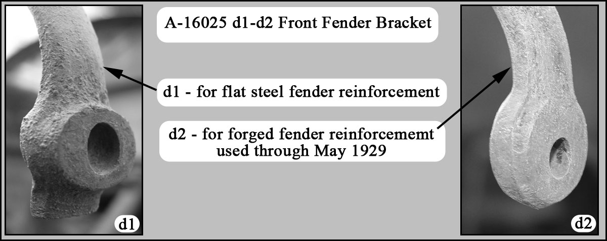
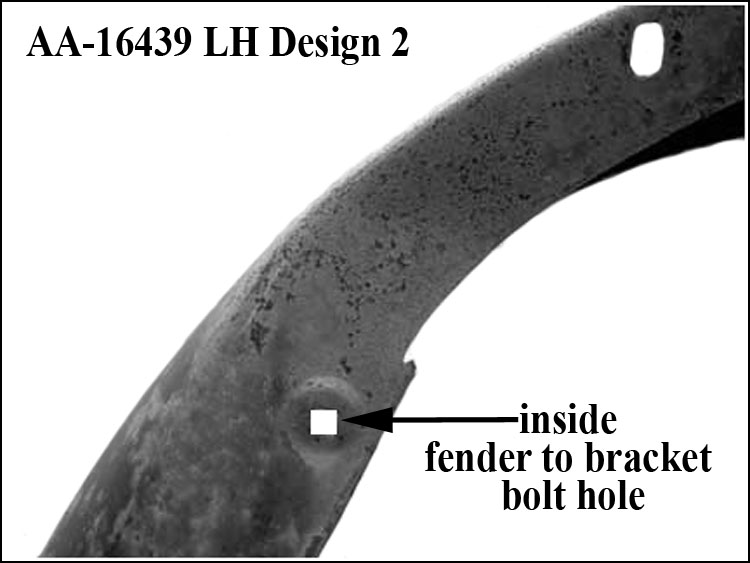
Reinforcement @ Bracket – For both the front and rear fenders, the reinforcement used at the fender-to-bracket bolt hole had two designs. The d1 reinforcement was flat steel attached to the fender with two spot weld’s. In mid-1928, d2 reinforcement was introduced. It was a forging attached with four spot weld’s. See the 12/27—6/30 gallery for examples.
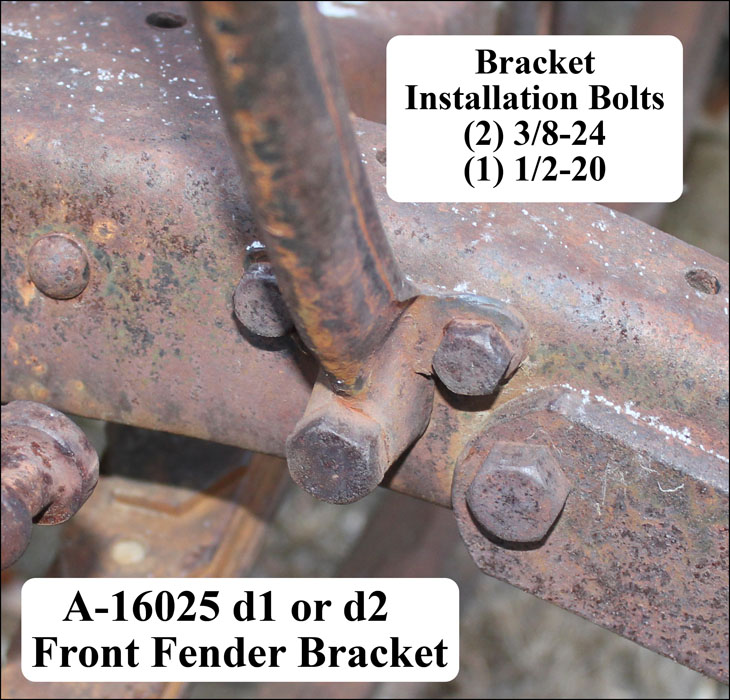
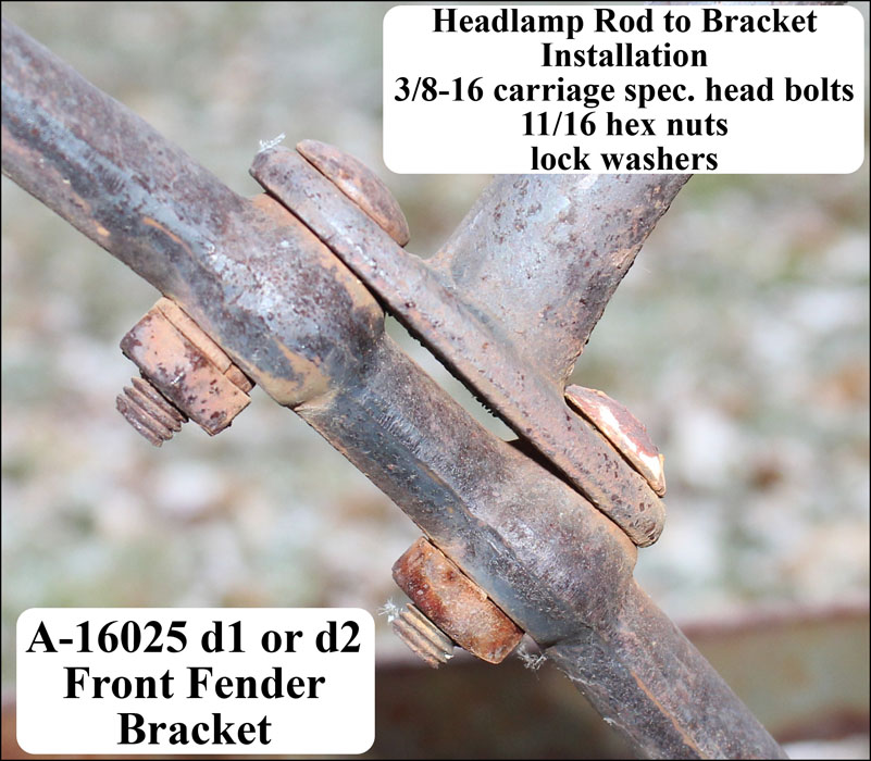
Bracket Designs (front fender) – A-chassis front fender bracket A-16025 was used. This bracket had several design changes. See the 12/27—6/30 gallery for examples.
- d1 – Fenders with the flat steel reinforcement used d1 forged fender brackets which had a square outer end and a 1/4″ raised round boss.
- d2 – Through May 1929, fenders with the forged reinforcement used d2 forged fender brackets which had a round outer end and no raised boss.
- d3—d5 – April—October 1929. These were stamped steel with a channel facing outward. Starting in April 1929 d3 was used. It had a straight sided triangular base. In July, the d4 bracket, with a larger triangular base and curved sides, was used. In October, the d5 bracket was used. It had a 4-1/4″ long, ribbed reinforcement spot welded to the lower base.
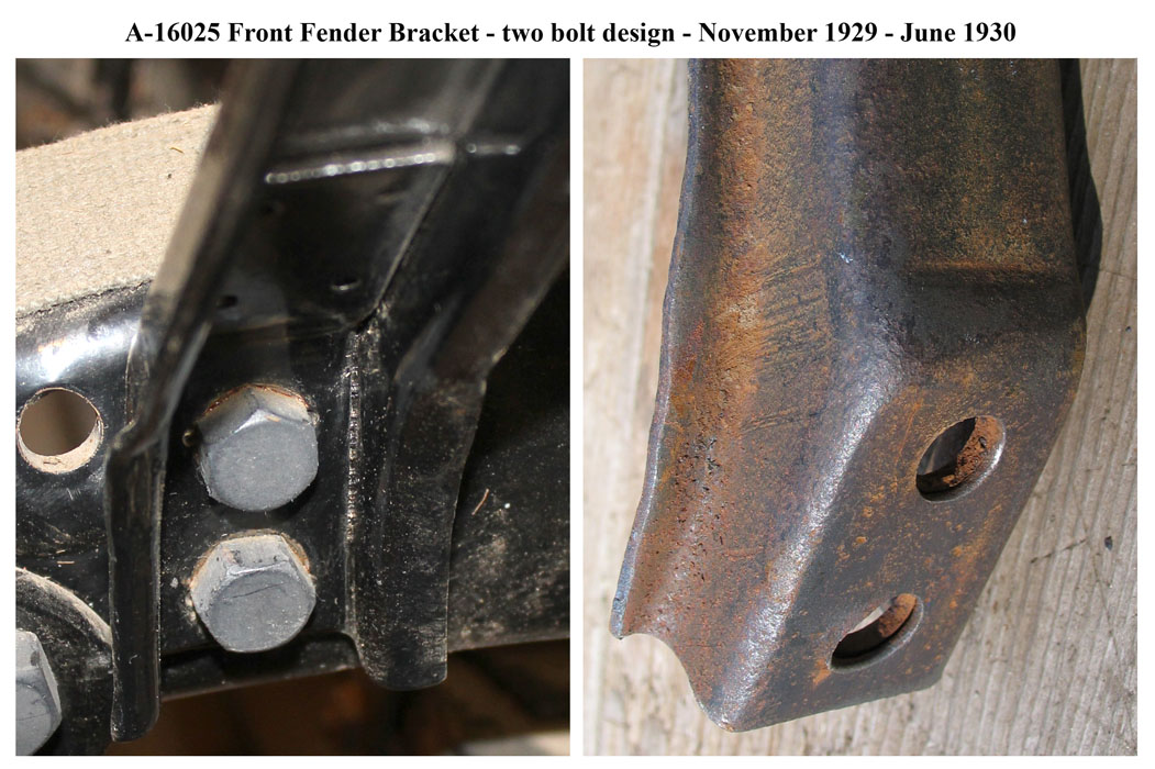
- d6 – 11/29—6/30. This A-16025 d6 bracket was stamped steel with a channel facing outward and had two vertical installation bolt holes. These holes had a reinforcement spot welded inside the channel.
Gallery (12/27—6/30 Front Fender+Bracket)


6/30—9/30 Fenders/Shields
For this date range, AA’s were assembled with “B” suffixed body types (i.e. 76-B Open Cab, 82-B Closed Cab, or 85-B Panel Delivery).
Front fenders A-16005-C/06-C d1 were used with these body types. They had fender shields spot welded to the fender which were fastened to separate running board shields.
Each fender had an embossed cup around the two 5/16″ front fender to frame mounting screw holes and the over-the-frame flange did not have a folded edge.
These fenders were the May 1930 designed A-chassis front fenders as indicated in Area 13 of the RGJS.
9/30—12/32 Fenders/Shields
AA’s without Fender Wheel Carriers – A-chassis front fenders A-16005-C/06-C d2 were used. This design was the same as the d1 fenders but the flange for the fender shield was designed to accommodate six slotted holes punched for using bolt-on fender shields.
A 5/8″ hole was added to the fender’s rear flange for assembly line conveyor hanging in March 1931. The hole was reduced to 1/2″ in May 1931.
The bolt-on fender shields for these fenders were assigned parts A-16029/30 (RH/LH). These were A-chassis part ids. On the assembly line, these fender shields were only used on the AA-chassis since the A-chassis was fit with a one-piece running board shields.
Note – Through service, the d2 fenders and separate bolt-on fender shields were provided when a prior fender assembly (with the spot-welded-on fender shield) was replaced for either the A or AA. The d1 fender assembly with spot-welded-on shield was not available for service starting in September 1930.
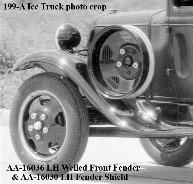
AA’s with Left Fender Wheel Carrier – Beginning February 1931, some AA’s were fit with a left fender wheel carrier. These AA’s used AA-16036 welled, left front fender and AA-16030 left fender shield.
This fender was the A-chassis style but with a larger wheel-well to accommodate AA tire sizes. The AA-16030 fender shield included a hole for the AA wheel carrier support and a rubber grommet.
This installation was standard equipment for the 199-A Ice Wagon, 229-A Service, 242-A Heavy Duty Express, 270-A Funeral Service, 275-A Funeral Coach, 280-A Ambulance, 285-A De Luxe Police Patrol, 300-A De Luxe Delivery, as well as all dump, coal, and garbage body types. This installation was factory optional equipment for the 290-A Standard Police Patrol.
Note that AA left, welled front fender would have been available through service on or after February 1931.
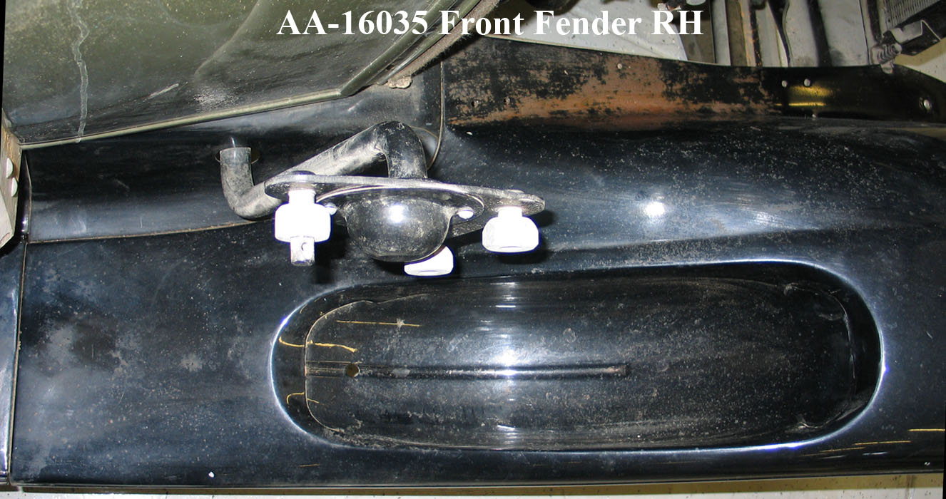
AA’s with Right Fender Wheel Carrier – A right front fender wheel carrier became available beginning in August 1931.
AA-16035 welled, right front fender and AA-16039 right fender shield was used for AA’s with this wheel carrier. The fender was the A-chassis style but with a larger wheel well to accommodate AA tire sizes.
The AA-16039 fender shield included a hole for the AA wheel carrier support and a rubber grommet.
This installation was standard equipment for the 315-A Standrive.
Note that AA right, welled front fender would have been available through service on or after August 1931.
6/30—12/32 Brackets (Front Fenders)
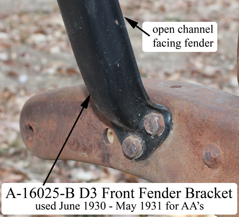
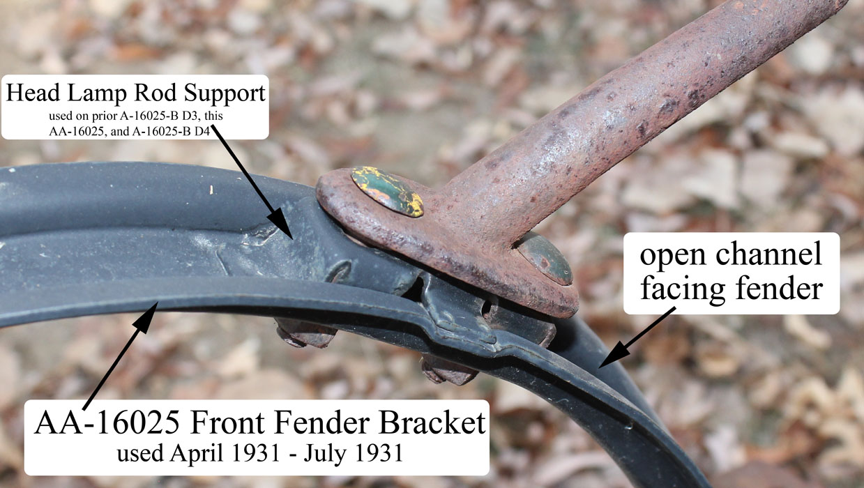
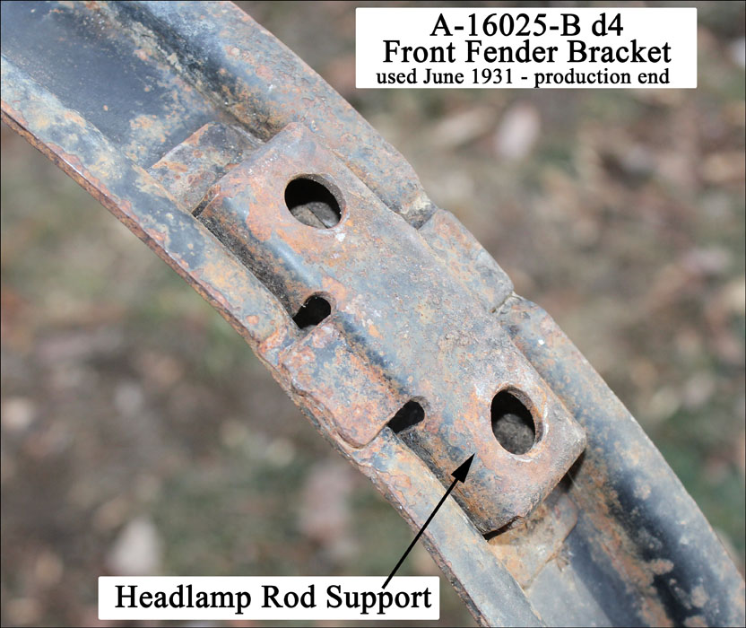
For 6/30—5/31 AA’s were fit with stamped steel A-16025-B d3 front fender brackets. It had an open channel facing the fender with a head lamp rod support spot welded in place.
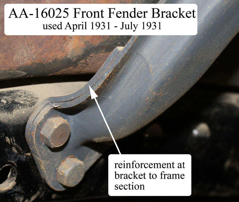
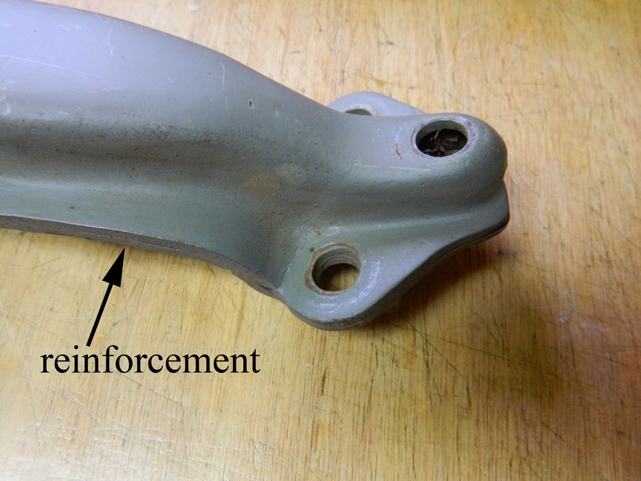
In April 1931, front fender bracket AA-16025 was adopted for all AA’s. It was the same as the A-chassis bracket but with an additional reinforcement spot welded to the bracket-to-frame section.
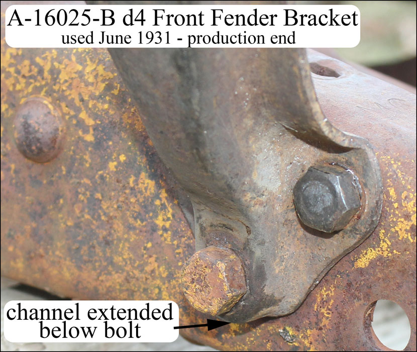
Just prior to being obsoleted, in June 1931, this AA bracket was strengthen by the extension of the channel down to include the lower bolt hole.
Starting 6/31, d4 of bracket A-16025-B was placed into production for both the A-chassis and AA-chassis. It was the same as the prior d3 bracket but was strengthened by the extension of the channel down to include the lower bolt hole. Refer to the 6/30-12/32 gallery below.
Gallery (6/30—12/32 Front Fender+Brackets)
Finish (Front Fender+Shield+Brackets)
Front fenders, front fender shields (starting 6/30), and fender brackets were dipped gloss, black enamel finished.
Fasteners (Front Fenders)
Fasteners (fender to bracket)
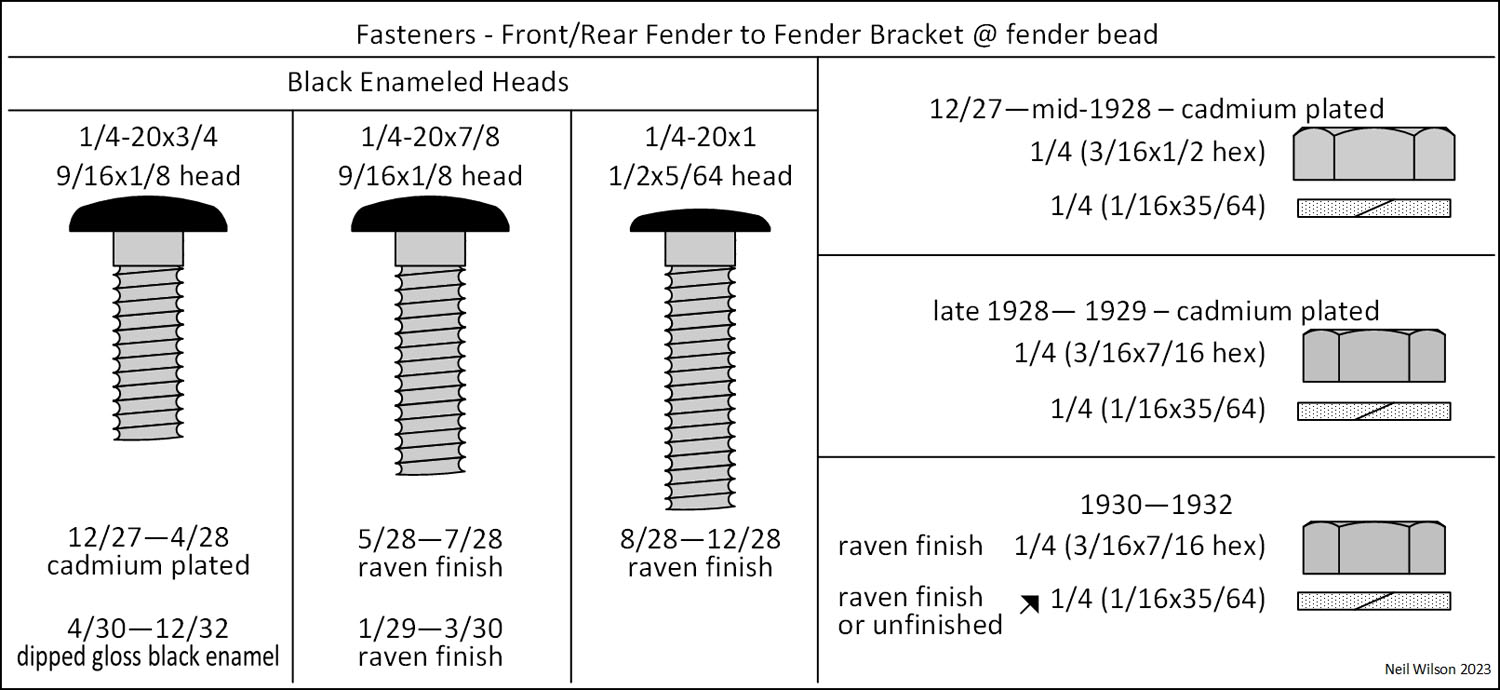
At the fender bead, for both front and rear fenders – several variations of fasteners were used as shown in the fasteners gallery.
Fasteners (front fender to frame)
- 12/27—6/30 – Same fasteners as for fenders to shield. Each fender had two bolts with heads facing up, flat washers under heads, lock washers, hex nuts. Note that the front bolt was covered by the hood shelves (covered in parts group A-16600)
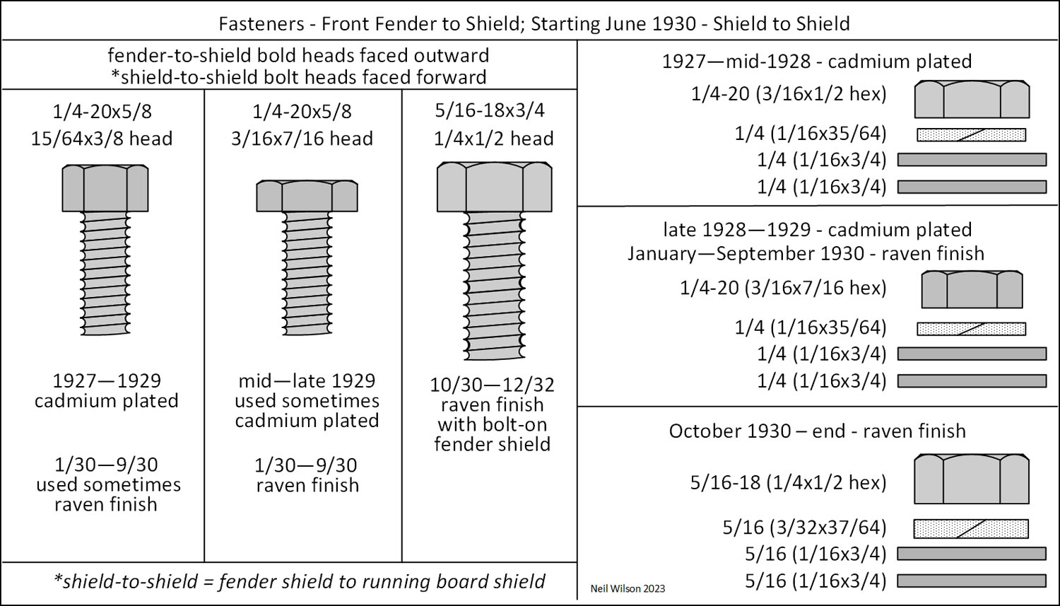
- Starting 6/30 (fenders had two embossed cup-shaped screw holes toward the front of the fender) – Two 1/4-20 x 7/8 oval head machine screws (black enameled heads), 7/16 hex nuts (raven finished), and lock washers (unfinished or raven). The front machine screws were for fastening the fenders to front shield.
Fasteners (front fender to shield)
Several variations of fasteners were used as shown in the fasteners gallery.
Fasteners (front fender to running board)
All fasteners were raven finished and bolt heads were on the running board side.
- 12/27—6/30 – (2) 5/16-18 x 3/4 carriage bolt, hex nut, flat washer, and lock washer
- 6/30—9/30 – Same fasteners as was used between the fender shield and running board shield. (3) 1/4-20 x 3/4 bolt, hex nut, flat washer (1, 2, or 0), and lock washer
- 10/30—12/32 – (3) 5/16-18 x 3/4 (1/2 hex head), nut (1/4 x 1/2 hex), flat washer (1/16 x 3/4), and lock washer
Fasteners (front fender bracket to frame)
Forged Brackets – One 1/2-20 x 1-9/16 bolt and two 3/8-24 bolts. Through 4/28, the bracket to frame bolts used castle nuts facing outward with unfinished cotter pins.
In addition, starting in early 1928 hex nuts with lock washers were used with bolt heads facing outward (note usage date overlap). Bolts were cadmium plated into late 1928 and gloss black thereafter.
Nuts were unfinished into late 1928 and zinc plated thereafter. Lock washers were unfinished.
Stamped Steel Brackets – 3/8-24 bolts, nuts, and lock washers with bolt heads faced outward. Bolts were gloss black. Nuts were zinc plated. Lock washers were unfinished. Bracket A-16025 d6 used two bolts. All other stamped steel brackets used three bolts.
Gallery (Fender Fasteners)
Anti-Squeak (Front Fenders)
Fender welting and frame webbing are common names used today. The fender anti-squeak was pre-cut around each fastener location as shown in the anti-squeak gallery.
The tail edge of the fender anti-squeak extended beyond the fender/shield joints (as viewed from under the fender). On-frame anti-squeak was most likely punched with holes for bolt.
Anti-Squeak (front fender to shield)
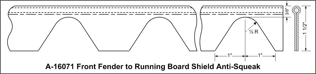
Anti-squeak parts were A-16071 (12/27—6/30) and A-16071-B (9/30—12/32 with bolt-on fender shields).
Front fender-to-shield anti-squeak was installed between the fender and shield. It was 1-1/2″ high. The bead was 3/16″ wide with a twisted paper core and was covered by a black pyroxylin coated fabric.
Anti-Squeak (front fender shield to running board shield)
Starting 6/30, AA’s had both fender and running board shields. The A-16071-C anti-squeak used between these two shields was 1/8” in diameter that was the same size as the gas tank anti-squeak.
Anti-Squeak (on-frame)
On-frame anti-squeak was located under the front-fenders and shields. The anti-squeak was 3/46″ to 1/16″ thick by 1-3/4″ wide. It extended from the front edge of the fenders rearward to where the shields left the frame. For the AA’s, the shields left the frame at the front body brackets.
Pieces of this anti-squeak were used between the shield and on-frame hood clip brackets as well as the on-frame body brackets.
Note – starting 6/30 (with the “B” suffixed body types), the front fenders extended forward beyond the frame. The anti-squeak was between the front fender and the front splash shield.
The anti-squeak gallery shows three photographs of reproduction on-frame anti-squeak installation.
The list of on-frame anti-squeak parts for the AA’s was:
- A-16540 – (12/27—6/30) front fender-to-frame
- A-16540-B (6/30—12/32) front fender-to-frame
- A-16070 – front fender to hood clip support bracket
- A-16542 – front fender to front body bracket
Gallery (Front Fenders Anti-Squeak)
Rear Fenders+Running-Boards+Running-Board-Shields
Original rear fenders, running boards, and running board shields used for a given AA are dependent on the body type, single or dual wheel equipment, and production date. Use the following table to determine original parts.
Parts are linked to detailed information following the table. Explanations of table columns are at the bottom of the table.
Parts followed by “d1” and/or “d2” designations indicate there were different designs for the same part.
Mobile screen horizontal avoids scrolling
Table (Parts Links)
| Parts Links for Rear Fenders – Running Boards – Running Board Shields | |||||||
|---|---|---|---|---|---|---|---|
| Type | Name | Wheels | Prod. Dates | Rear Fenders | Running Boards | RB Shields | Notes |
| Neil Wilson 2017 | |||||||
| ……AA’s with Rear Fenders (closed bodies, express bodies – except 239-A Meat Packers Express, and 88-A Platform with optional rear fenders) | |||||||
| 85-A | Panel Delivery | single | 08/28 06/30 | AA 16438/39 d2 | AA 16459 d1-d2 | AA 16538/36 d2 | frame side carrier |
| 85-B | Panel Delivery | single | 06/30 end | AA 16438-B/39-B | AA 16458-B/59-B | AA 16535-B/36-B | frame side carrier |
| dual | 12/31 end | AA 16308/09 | AA 16508/09 | AA 16535-B/36-B | |||
| 88-A | Platform | single | 12/27 er/28 | AA 16428/29 | AA 16459 d1 | AA 16535/36 d1 | optional equipment |
| er/28 07/29 | AA 16438/39 d2 | AA 16459 d1-d2 | AA 16535/36 d1-d2 | optional equipment | |||
| 89-A | Express | single | 12/27 er/28 | AA 16438/39 d1 | AA 16459 d1 | AA 16535/36 d1 | |
| er/28 md/29 | AA 16438/39 d2 | AA 16459 d1-d2 | AA 16535/36 d1-d2 | on-body carrier | |||
| lt/28 06/30 | AA 16438/39 d2 | AA 16459 d1-d2 | AA 16538/36 d2 | frame side carrier | |||
| 06/30 12/30 | AA 16438-C/39-C | AA 16458-B/59-B | AA 16535-B/36-B | frame side carrier | |||
| 195-A | Express – light duty | single | all | AA 16413/14 | AA 16458-B/59-B | AA 16534/36-B | |
| dual | 03/31 end | AA 16312/13 | AA 16508/09 | AA 16534/36-B | |||
| 197-A | Express – light duty | single | all | AA 16413/14 | AA 16468/69 | AA 16585/86 | |
| dual | 03/31 end | AA 16312/13 | AA 16500/01 | AA 16585/86 | |||
| 199-A | Ice Wagon | dual | all | AA 16403 | AA 16514-B/15-B | AA 16598-B/99-B | |
| 210-A | Panel Delivery | dual | all | AA 16310/11 | AA 16500/01 | AA 16585/86 | |
| 229-A | Service | single | 1/31 er/31 | AA 16438-B/39-B | AA 16458-B/59-B | AA 16535-B/36-B | frame side carrier |
| er/31 end | AA 16438-B/39-B | AA 16458-B/59-B | AA 16534/36-B | ||||
| dual | 12/31 end | AA 16308/09 | AA 16508/09 | AA 16534/36-B | |||
| 242-A | Express – heavy duty | dual | all | AA 16403 | AA 16514-B/15-B | AA 16598-B/99-B | |
| 270-A | Funeral Service | single | all | AA 16413/14 | AA 16458-B/59-B | AA 16534/36-B | |
| 275-A | Funeral Coach | single | er/31 08/31 | AA 16413/14 | AA 16458-B/59-B | AA 16534/36-B | |
| 09/31 end | AA 16413/14 | AA 16475/76 | AA 16534/36-B | linoleum covered | |||
| 280-A | Ambulance | single | er/31 08/31 | AA 16413/14 | AA 16458-B/59-B | AA 16534/36-B | |
| 09/31 end | AA 16413/14 | AA 16475/76 | AA 16534/36-B | linoleum covered | |||
| dual | 03/31 end | AA 16312/13 | AA 16508/09 | AA 16534/36-B | |||
| 285-A | De Luxe Police Patrol | single | all | AA 16413/14 | AA 16458-B/59-B | AA 16534/36-B | |
| dual | 03/31 end | AA 16312/13 | AA 16508/09 | AA 16534/36-B | |||
| 290-A | Standard Police Patrol | single | all | AA 16438-B/39-B | AA 16458-B/59-B | AA 16535-B/36-B | frame side carrier |
| dual | 12/31 end | AA 16308/09 | AA 16508/09 | AA 16534/36-B | optional fender carrier | ||
| 12/31 end | AA 16308/09 | AA 16508/09 | AA 16535-B/36-B | frame side carrier | |||
| 300-A | De Luxe Delivery | single | all | AA 16413/14 | AA 16458-B/59-B | AA 16534/36-B | |
| dual | 03/31 end | AA 16312/13 | AA 16508/09 | AA 16534/36-B | |||
| 315-A | Standrive | single | 08/31 11/31 | part unknown | none | none | standard equipment |
| 11/31 07/32 | used rub rail | none | none | standard equipment | |||
| 11/31 07/32 | part unknown | none | none | special equipment | |||
| dual | 12/31 07/32 | AA 16310/11 | none | none | special equipment | ||
| 330-A | School Bus (S.B.) | dual | all | Union City fender | AA 16514-B/15-B | none | |
| 330-B | Passenger Bus (P.B.) | dual | all | Union City fender | AA 16514-B/15-B | none | |
| .…..AA’s without Rear Fenders (includes AA’s not listed above as well as type 88-A Platform without factory optional rear fenders) | |||||||
| Other.. | open cargo body | either | 12/27 06/30 | none | AA 16514/15 d1-d2 | AA 16598/99 d1-d2 | |
| Other.. | open cargo body | either | 06/30 end | none | AA 16514-B/15-B | AA 16598-B/99-B | with 20″ wheels |
| Other.. | open cargo body | single | 07/31 end | none | AA 16514-C/15-C | AA 16598-B/99-B | with 18″ wheels |
Column Explanations
Type column – Body type code (Ford assigned). For AA’s without rear fenders, “other” is noted in this column (bottom three table lines).
Name column – Body type name (Ford assigned). For AA’s without rear fenders, “open cargo body” is noted in this column (bottom three table lines).
Wheels column – The rear axle wheel configuration – single (single rear wheel equipment), dual (dual wheel equipment). This directly effects which rear fenders and running boards were used for the vehicle.
Prod. Date column – A production date range for when the rear fenders, running boards, and running board shields were used. “start” = production start; “end” = production end; a date beginning with “er” = early (Jan., Feb., March, April), “md” = mid (May, June, July, Aug.) or “lt” = late (Sept., Oct., Nov., Dec.).
Rear Fenders column – The right and left rear fender part ids for the body type, wheel equipment, and production date range (e.g. for “AA-16308/09” – AA-16308 was the right rear fender and AA-16309 was the left rear fender). Note that rear fender AA-16403 was used on both sides.
Running Boards column – The right and left running board part ids for the body type, wheel equipment, and production date range (e.g. for “AA-16458-B/59-B” – AA-16458-B was the right running board and AA-16458-B was the left running board). Note that running board AA-16459 was used on both sides.
RB Shields column – The right and left running board shield part ids for the body type, wheel equipment, and production date range (e.g. for “AA-16538/36” – AA-16538 was the right shield and AA-16536 was the left shield).
Notes column – Additional information about the vehicle or parts. Optional or special equipment indicates parts which were factory available.
AA Rear Fenders
General Information (Rear Fenders)
Usage (Rear Fenders)
There were ten different AA rear fenders. One fender was used on both the right and left side. All others had right and left hand fenders.
There were five rear fenders for AA’s with single rear wheel equipment and five for AA’s with dual rear wheel equipment. To determine which of the ten rear fenders were for a given body type refer to the parts links table.
The table’s fender part ids are linked to the fender descriptions below which are in part number sequence (i.e. in numerical sequence). So, it is best to use the table links!
Design (Rear Fenders)
Except for fender AA-16403, AA rear fenders were 46″ (plus or minus 3/4″) from the running board reinforcement to the slightly curved tail edge. They were designed like A-chassis rear fenders with a bead (i.e. a raised ridge) along the fender’s outside edge. They had a wire crimped onto the serrated outside edge, tail edge, and a portion of the inside edge up to the body.
Finish (Rear Fenders)
All rear fenders were dipped, gloss, black enamel finished. For rear fenders with an inside mounting flange, there may have been paint drain holes at the upper center where the flange starts.
Fasteners (Rear Fenders)
- Rear fender to body – find a specific body type in the parts links table.
- Fender to bracket (at bead) – for both the front and rear fender – several variations of fasteners were used as shown in the fender fasteners gallery.
- Rear fender to bracket (at inside of fender) – find a specific body type in the parts links table.
- Rear fender to running board – 5/16-18 x 3/4 carriage bolt with head on the fender side, flat washer (1/16 x 3/4), lock washer, and hex nut. All fasteners were raven finished.
- Rear fender to shield – A-chassis fender fasteners were used:
- 12/27—1/29 – Bolts were 1/4-20 x 5/8 with a 3/8 hex thick head bolt, a hex nut (3/16 x 1/2), two flat washers (1/16 x 3/4 diameter) and a 1/4 lock washer. All fasteners were cadmium plated. In late 1928 the nut was changed from a 1/2 to a 7/16 hex through 1929. For 1930 production, these were raven finished. Bolt heads faced inward.
- 11/28—mid-1930 – a 1/4-20 x 9/16 special head carriage bolt (approximately 3/4 diameter) could also have been used. Initially the bolt was cadmium plated and changed to raven finish with a dipped gloss black enamel head in December 1928. The bolt head faced inward.
- 1/30—10/30* – 1/4-20 x 9/16 special (large) head carriage bolt, flat washer, lock washer and hex nut. All were raven finish and the carriage bolt head was a dipped gloss black enamel. The bolt head faced inward.
- 10/30—1931* – Bolts were changed to 5/16-18 x 3/4 with a 1/2 hex head. A hex nut (1/2 x 1/2), two flat washers (1/16 x 3/4) and a 5/16 lock washer were used at each location. All fasteners were raven finished. The bolt head faced outward.
* The change in fasteners corresponds with the change in the fenders, running boards and shields, which began in 10/30 and was completed in 12/30.
Anti-Squeak (Rear Fenders)
Rear fender anti-squeak was installed between the fender, shield, fender spacer (where applicable), and cargo body. The bead was 3/16″ wide with a twisted paper core and was covered by a black pyroxylin coated fabric. The anti-squeak was pre-cut around each fastener location as shown in the drawing.
Note: Fender welting is a common name used today. The drawing is of the front fender anti-squeak. But the rear anti-squeak had the same design.
By Part# (Rear Fenders)
Listed below are descriptions of the ten AA rear fenders used in the 12/27—12/32 production of body types fit with rear fenders.
These rear fenders are listed in part number sequence. These descriptions can be read through for details if desired.
However, to view a rear fender description for a given body type, use the parts links table.
In this table – find a body type and use the rear fender link for direct access to the rear fender description.
AA-16308/09 (RH/LH) Rear Fender (with dual wheels)
Available starting 12/31 for the following body types when fit with factory optional dual wheel equipment:
85-B Panel Delivery
229-A Service
290-A Standard Police Patrol
They were a wider version of the single wheel equipment fenders. The wheelhouses of the bodies were the same for either the single or dual wheel equipment. Therefore, the installation fasteners were the same as was used for the AA-16438-B/39-B (RH/LH) single wheel equipment fenders.
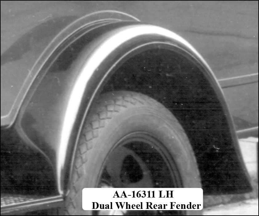
AA-16310/11 (RH/LH) Rear Fenders (with dual wheels)
These fenders were for the following body types:
210-A Panel Delivery
315-A Standrive
Dual wheel equipment was standard for the 210-A. For the 315-A, dual wheel equipment was special factory equipment beginning in December 1931.
Fender brackets were not used with these fenders. Consequently there were no corresponding fender to bracket bolts in the bead. The fender tail was curved like other A and AA rear fenders.
Rear Fender to Body – These fasteners are currently not known. Anyone with information, please make Contacts.
AA-16312/13 (RH/LH) Rear Fenders (with dual wheels)
When fit with factory optional dual wheel equipment, these fenders were available starting March 1931 for the following body types:
195-A Express
197-A Express
280-A Ambulance
285-A De Luxe Police Patrol
300-A De Luxe Delivery
These fenders had an outside bead with a crimped on wire edging like other A and AA chassis rear fenders. However, the wire edging following the fender perimeter from the front corner at the running board to the fender-to-shield flange at the rear.
Rear fender fasteners which were unique to these fenders is provided below (see the general rear fender fasteners otherwise):
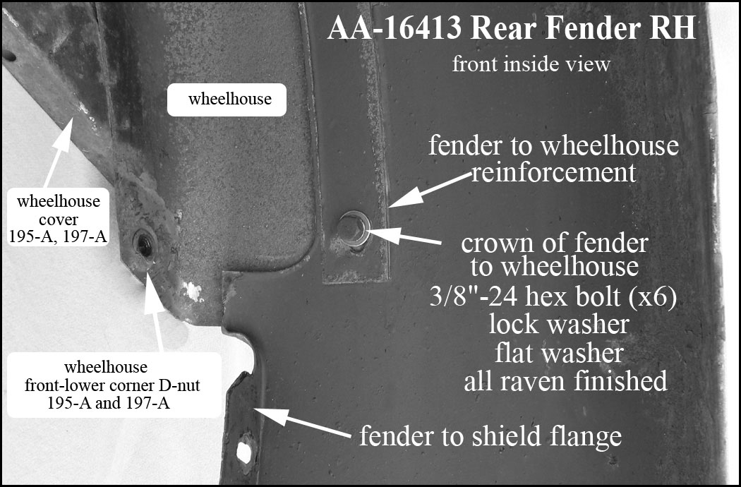
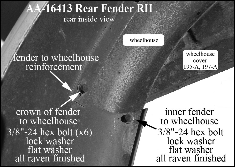
Rear Fender to Body – Fasteners were raven finished. Depending on the wheelhouse, there were six or eight 3/8-24 hex bolts with lock and flat washers used to install each fender. Six oblong holes (over the crown of the fender) were provided for installing bolts into the wheelhouse D-nuts . For the 195-A and 197-A, two additional bolts were used to attach the fender to the wheelhouse D-nuts located at the front and rear lower corners.
Rear Fender to Fender Bracket – These fenders did not used fender brackets.
AA-16403 Rear Fender (with dual wheels)
This fender was for the following body types that was fit with dual wheels as standard equipment.
199-A Ice Wagon
242-A Heavy Duty Express
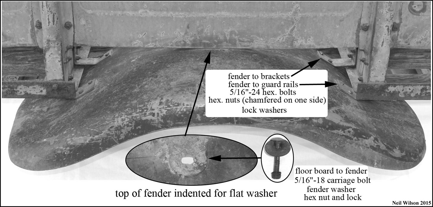
This fender was designed to be used on both sides of the body with both ends being symmetrical. It did not have an edge bead but did have a wire crimped to the entire perimeter.
Rear fender fasteners which were unique to these fenders is as follows (see the general rear fender fasteners otherwise):
Rear Fender to Body – The fenders were bolted through the overhead floor boards. An indentation in the top of the fender allowed a large diameter, fender washer to fit flat in the indentation. See the AA-16403 photograph for detail.
Rear Fender to Fender Bracket – There were two fender brackets bolted to the cross sills toward the inner side of the fender and the fenders were bolted to the guard rails. See the AA-16403 photograph for detail.
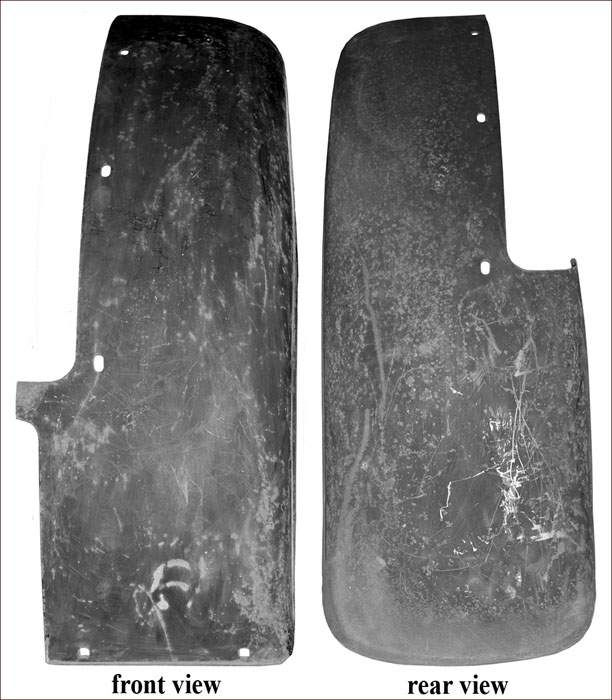
AA-16413/14 (RH/LH) Rear Fenders (with single wheels)
These fenders were for the following body types that were fit with single wheel equipment as standard:
195-A Express
197-A Express
270-A Funeral Service
275-A Funeral Coach
280-A Ambulance
285-A De Luxe Police Patrol
300-A De Luxe Delivery
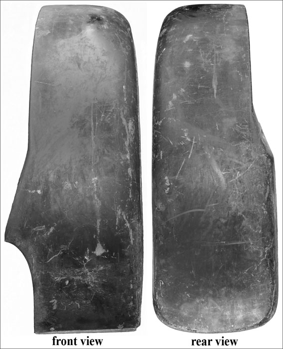
The unique design of these fenders is shown in the AA-16413/14 gallery. When installed, they looked like other A and AA chassis rear fenders. However, there were no fender brackets used with these fenders and therefore no bracket bolt hole or reinforcement in the bead. The body types using these fenders had wheelhouses for fender installation.
Rear fender fasteners which were unique to these fenders is provided below (see the general rear fender fasteners otherwise):
These fenders used the d2 running board reinforcement at the forward, lower edge. This reinforcement plate included a ribbed flange along the top and an “L” flange along the bottom.
Rear Fender to Body – The under-fender-to-wheelhouse installation for the 195-A and 197-A Express bodies is shown in the AA-16413/14 gallery. Each fender’s mounting edge had a reinforcement spot welded in place with six oblong mounting holes for 3/8″-24 hex bolts, lock and flat washers. The same fasteners were used to bolt the inner fender to the wheelhouse as shown. D-nuts were installed in the wheelhouse for these fasteners.
Rear Fender to Fender Bracket – No rear fender brackets were used with these rear fenders.
Gallery – AA-16413/14 Rear Fenders
AA-16428/29 (RH/LH) Rear Fenders (with single wheels)
These fenders were optional factory equipment for body type:
88-A Platform
They were designed to fit the early 1928 88-A Platform which did not have fender cutouts in cross sills #3 and #4.
Unique rear fender brackets (two on each side) attached the fenders to each of the #3 and #4 cross sills.
An example has not been found. If you have any information/photographs, please sent an email (see Contacts).
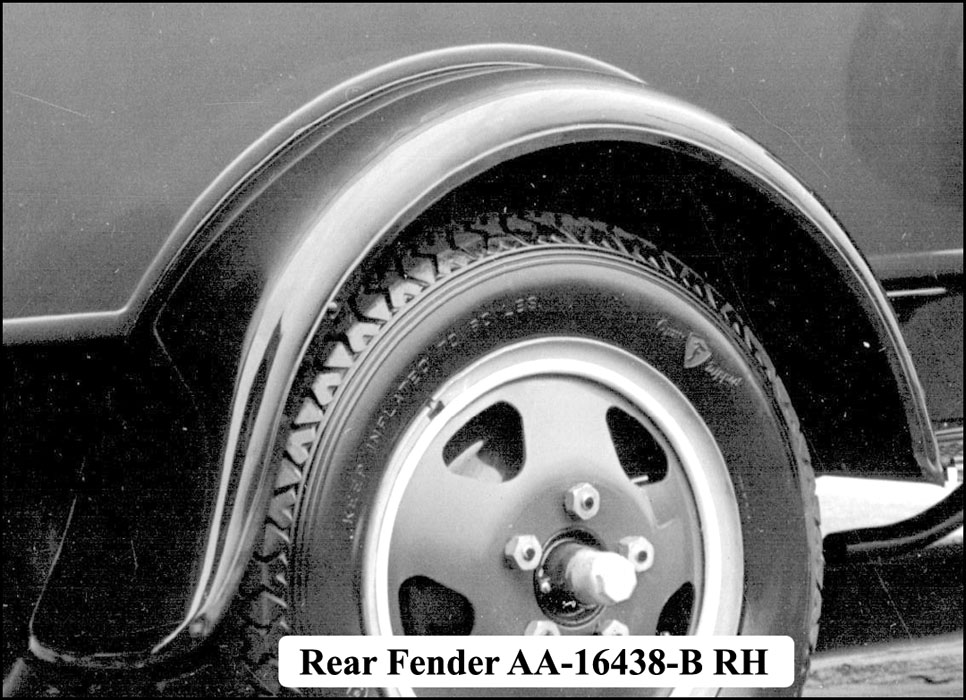
AA-16438/39 (RH/LH) Rear Fenders (with single wheels)
These fenders were for the following body types:
89-A Express
85-A Panel Delivery
88-A Platform
There were two designs for these fenders:
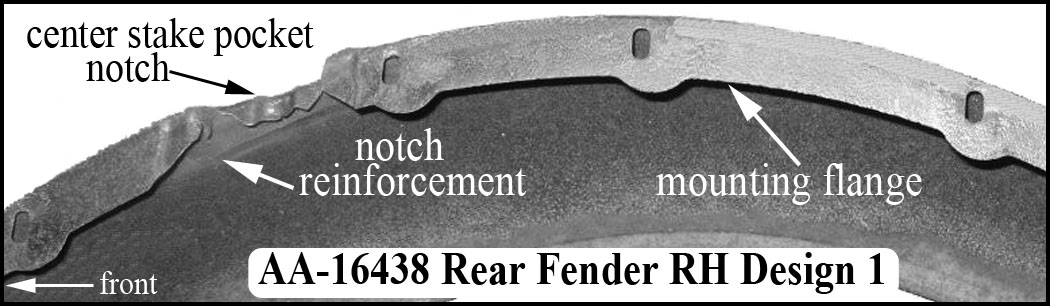
d1 – Fenders were for body type 89-A Express with a long center stake pocket on each body side.
These fenders were designed with flanged, reinforced notches that allowed the fenders to fit around the express body’s long center stake pockets. The body-mounting flange was a scalloped design. The AA-16438/39 gallery shows the fender notch and scalloped design flange.
The reinforcing plate for the fender bracket was flat steel (installed with two spot welds) as shown in the AA-16438/39 gallery. The reinforcing plate at the running board was a flat plate.
d2 – Fenders for body types 85-A Panel Delivery, 88-A Platform, and 89-A Express with a short center stake pocket on each body side. See AA-16438/39 gallery. Fender production changes for d2 were as follows:
- Early 1928 – Fenders were the same as the d1 fenders but without the notches for the 89-A long center stake pocket.
- April 1928 – The fender bracket reinforcement was changed to a steel forging (installed with four spot welds). See AA-16438/39 gallery.
- May 1928 – The body-mounting flange was increased to a constant width of 1-7/16” that eliminated the previous scalloped flange design.
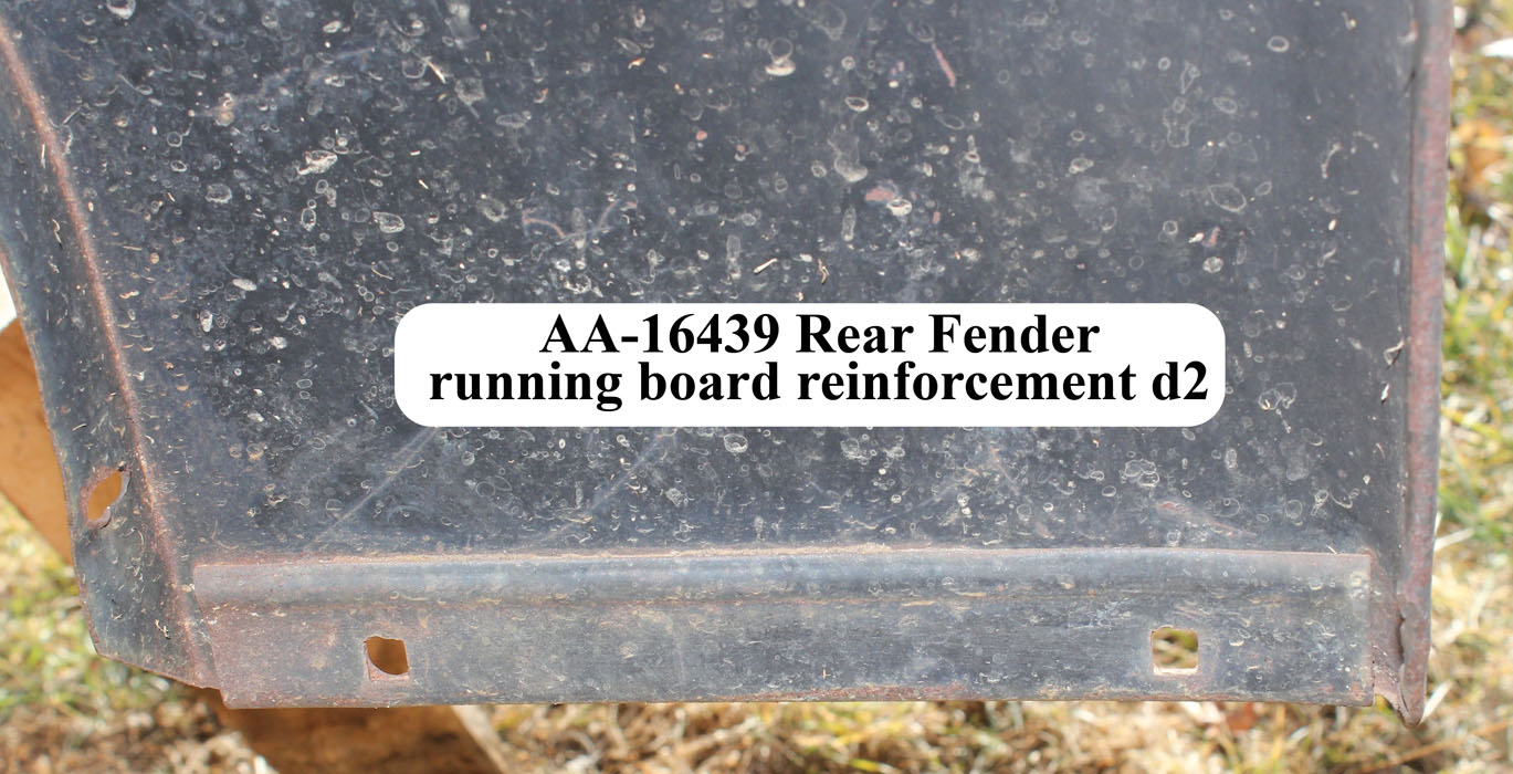
- June 1928 – A d2 fender-to-running-board reinforcement plate was used. It included a ribbed flange along the top and an “L” flange along the bottom.
Gallery – AA-16438/39 Rear Fenders
Fasteners (AA-16438/39 Rear Fenders)
All fasteners were raven finished. Rear fender fasteners unique to these fenders are provided below. See the general rear fender fasteners otherwise:
Rear Fender to Body
- 85-A Panel Delivery – (5) 5/16-18 hex nuts, lock and flat washers. One 1/4-28 hex bolt, lock and flat washer at the lower fender spacer hole into a body installed D-nut.
- 88-A Platform – (3) 5/16-18 hex bolts, hex nuts and 5/16 (3/32 x 23/32) lock washer – fender to brace on body. The 23/32 OD lock washers are also used for 88-A floor to support structure assembly. If using smaller OD lock washers, use a flat washer to spans the oblong fender holes.
- 89-A Express – (5) 5/16-18 carriage bolts with heads on the inside of the body, flat washers, lock washers, and hex nuts.
Rear Fender to Fender Bracket
Fastener at inside of fender.
- 85-A Panel Delivery – 1/4-28 hex bolt and lock washer into body mounted D-nut
- 88-A Platform – used same fasteners as fender bead fasteners (see fender fasteners gallery) but with appropriate bolt length for forged or stamped steel brackets
- 89-A Express – used same fasteners as fender bead fasteners (see fender fasteners gallery) but with appropriate bolt length for forged or stamped steel brackets.
Fender Bracket (forged steel) to Body
- 85-A Panel Delivery – (3) 5/16-24 hex bolts and lock washers
- 88-A Platform – for brackets with square holes – (3) 5/16-18 x 2-1/2 carriage bolts* or for bracket with round holes – (3) 5/16-18 x 2-1/2 hex bolts*. Plus flat washers, lock washers and 5/16-18 (1/4 x 9/16) square nuts (chamfered 1 side). *Note: sills can be various thickness – use bolt length which leaves about 1/8″ extension past nut.
- 89-A Express – for bracket with square holes – (3) 5/16-18 x 3 carriage bolts or for bracket with round holes – (3) 5/16-18 x 3 hex bolts. In addition, lock washers and 5/16-18 hex nuts.
AA-16438-B/39-B (RH/LH) Rear Fenders (with single wheels)
These fenders were for the following body types when fit with the production standard single wheel equipment:
85-B Panel Delivery
229-A Service
290-A Standard Police Patrol
Fasteners (AA-16438-B/39-B Rear Fenders)
Rear fender fasteners which were unique to these fenders is provided following (see the general rear fender fasteners otherwise):
Rear Fender to Body
(5) 5/16″-18 hex nuts, lock and flat washers. One 1/4-20 or 28 as appropriate, hex bolt, lock and flat washer at the lower fender bolt hole into a body threaded hole. The 229-A, for example, had a caged 1/4-20 square nut installed on the inside of the wheel well.
Rear Fender to Fender Bracket (at inside of fender)
1/4-20 or 28 as appropriate, hex bolt and lock washer into a threaded body hole. The 229-A, for example, had a caged 1/4-20 square nut installed on the inside of the wheel well for the inside fender to bracket bolt.
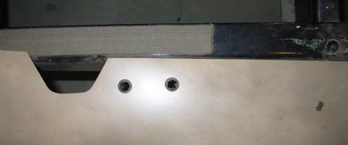
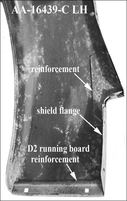
AA-16438-C/39-C (RH/LH) Rear Fenders (with single wheels)
These fenders were for one unique body/cab setup:
89-A Express with 82-B Closed Cab
They were the same as the prior d2 fenders used with the 82-A Closed Cab (i.e. fenders AA-16438-B/39-B) except for the fender-to-shield section. Both the shield flange and corresponding reinforcement bracket were redesigned to fit the new running board shield design. See the AA-16439-C photograph.
These fenders used the same 89-A fasteners listed in for the AA-16438/39 fasteners rear fenders.
Union City Rear Fenders (with dual wheels)
These fender assemblies were supplied by Union City with the following body types:
330-A School Bus
330-B Passenger Bus
There was a flat inner skirt welded to the fender and extended down to the top of the chassis frame. Installed, the assembly was visible as a hump on the inside of the bus. The fenders were flat across the front and rear edges and extend below the body a few inches. Fenders had a flat outer flange with no bead. There were no rear fender brackets used with these fenders.
Rear Fender to Body Fasteners
Each fender was installed with nine bolts. About 12″ from the bottom, there were three front and three rear bolts. There were three bolts at the outside top edge of the crown. These 5/16″ bolts, each with a lock washer, flat washer and fender washer, were inserted from the underside of the fender through oval holes with lock washers and square nuts securing the bolts to the bus frame. The lower edge of the skirt had two 1/4″ bolts inserted from underneath the body secured with a fender washer, flat washer, lock washer, and square nut.
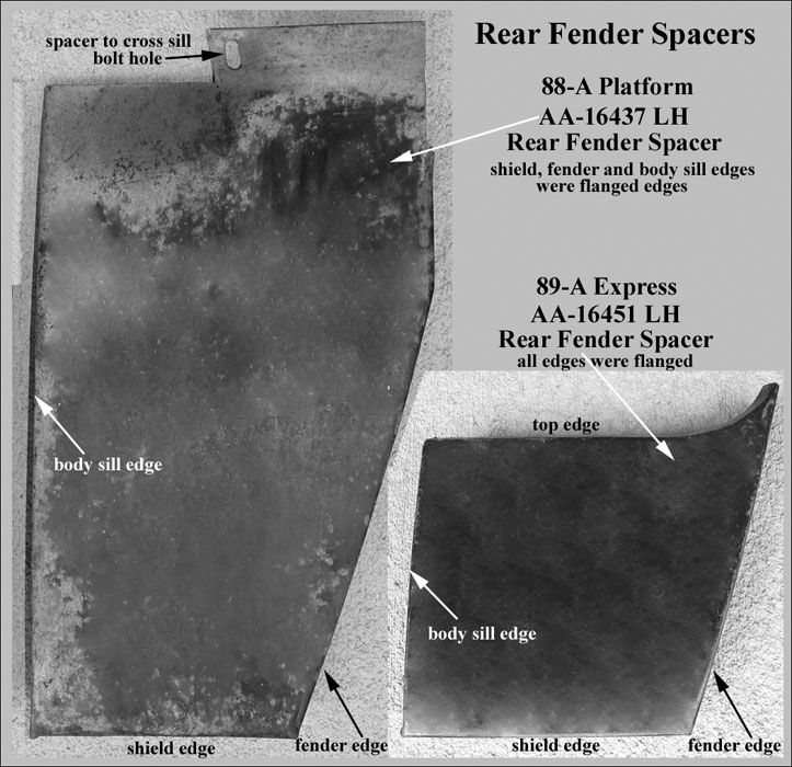
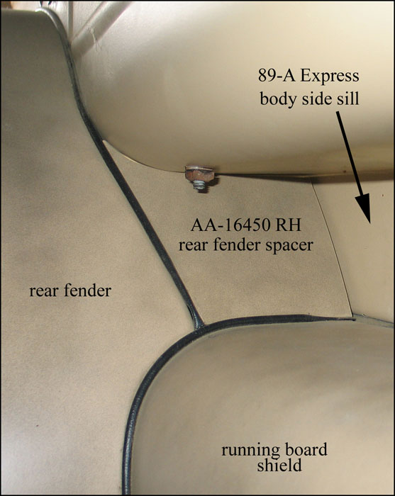
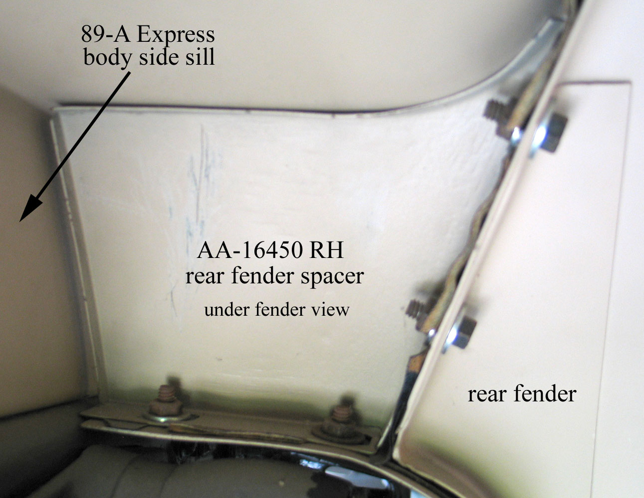
AA Rear Fender Spacers
General Information (Rear Fender Spacers)
The 88-A Platform (with factory optional rear fenders) and the 89-A Express used rear fender spacers.
These spacers filled the opening above the running board shield, the inside of the rear fender and the cargo body sill.
The 88-A Platform optional rear fenders were available through July 1929.
The 89-A Express production lasted through December 1930.
The spacers gallery shows the spacers for the two body types. These stamped steel spacers were dipped, gloss black enamel.
Gallery (Rear Fender Spacers)
Anti-Squeak (Rear Fender Spacers)
For the 89-A Express, there was anti-squeak between the fender spacer and the running board shield as shown in the spacers gallery. This anti-squeak extended down to the running board.
For the 88-A Platform there was no anti-squeak between the fender spacer and the running board shield.
Note – Fender anti-squeak (welting) is covered under Front Fenders and Rear Fenders.
Fasteners (Rear Fender Spacers)
All fasteners were cadmium plated 12/27—12/29 and raven finished for 1930:
Spacer to fender – (2 bolts) – 88-A and 89-A
- bolt – 1/4-20 x 5/8 (3/8 hex thick head) – head on fender side
- nut – 1/4-20 (3/16 x 1/2 hex) – 7/16 hex beginning in late 1928
- flat washers (2) – 1/16 x 3/4
- lock washer – 1/4
Spacer to sill – (1 screw – 88-A only)
- screw – #12 x 1 round head, slotted – unfinished
Spacer to 88-A cross sill – (1 bolt)
- bolt – 1/4-20 x 5/8 (3/8 hex thick head) – head on spacer side
- nut – 1/4-20 (3/16 x 1/2 hex) – 7/16 hex beginning in late 1928
- flat washers (1) – 1/16 x 3/4 – under bolt head
- lock washer – 1/4
Spacer to shield – (2 bolts – 89-A only)
- step bolt – 1/4-20 x 9/16 (3/4 diameter head) – head on bottom side of shield
- nut – 1/4-20 (3/16 x 1/2 hex) – 7/16 hex beginning in late 1928
- flat washer – 1/16 x 3/4
- lock washer – 1/4
Brackets (Rear Fender)
General Information (Rear Fender Brackets)
No Bracket Body Types
The following body types with dual wheel equipment did not have rear fender brackets:
197-A Express, 210-A Panel Delivery, 275-A Funeral Coach, 280-A Ambulance, 285-A De Luxe Police Patrol, 300-A De Luxe Delivery
Finish (Rear Fender Brackets)
The 242-A HD Express and 199-A Ice Wagon rear fender brackets were installed on the #3 and #4 body cross members and then painted body color.
All other rear fender brackets were dipped black enamel finished. Fender bracket to body or frame bolts were black enamel and the washers were raven finished.
By Body-Type (Rear Fender Brackets)
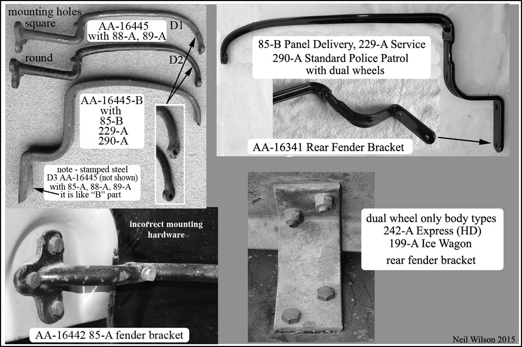
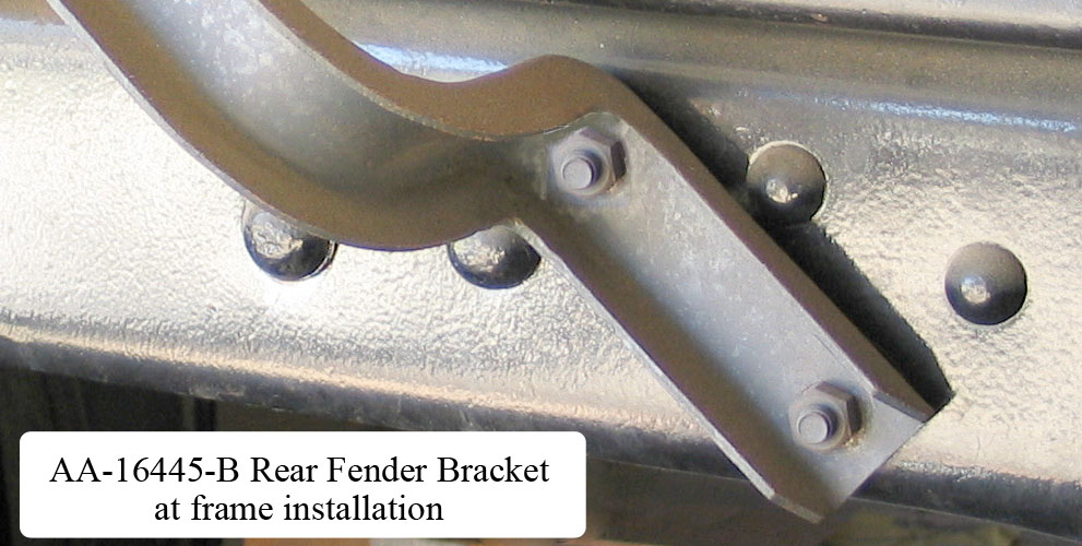
89-A Express (Rear Fender Brackets)
Refer to the bracket photograph for bracket details. From the beginning of production, AA-16445, forged steel, rear fender brackets were used. The brackets were attach to the body side sills with the same, three, 5/16-18 bolts as was use for the body rear cross member.
The outer end of the d1 bracket had a square outer end and a 1/4″ raised round boss. It was designed for fenders with a flat, sheet metal, fender-to-bracket reinforcement. The bracket-to-sill installation end had three square, carriage bolt, installation holes.
In July 1928, the fender-to-bracket reinforcement was changed to a forging. The d2 AA-16445 fender bracket, with a round outer end and no raised boss, was used with these fenders. The d2 bracket had three round bracket-to-sill installation holes for hex bolts. In December 1928, a stamped steel bracket (d3) was released which attached to the frame. Bracket to frame fasteners were two 5/16-24 hex bolts, hex nuts (chamfered on one side), and lock washers. Both the d2 forged and d3 stamped designs were used thereafter.
88-A Platform (Rear Fender Brackets)
Rear fenders were a production option for the 88-A Platform through July 1929. Refer to the bracket photograph for bracket details.
Initially, unique rear fenders with two stamped steel brackets per side were used. Brackets attached the rear fender to the #3 and #4 platform cross members. No photograph is available at this time. An example has not been found.
If you have any information/photographs, please sent an email (see Contacts).
In April 1928, modifications were made to the 88-A Platform and 89-A Express so that both body types used the same rear fenders. The AA-16445 (d1—d3) rear fender brackets were used with the 88-A beginning in April 1928.
Refer to the 89-A Express for usage dates.
Bracket fasteners were as follows:
d1 brackets were attached to the body sills with three 5/16-18 carriage bolts, flat washers, square nuts, and lock washers.
d2 brackets were attached to the body sills with 5/16-18 hex bolts, flat washers, hex nuts (chamfered on one side), and lock washers.
d3 brackets were attached to the frame with two 5/16-24 hex bolts, hex nuts (chamfered on one side), and lock washers. The bolt was installed from the inside of the frame.
85-A Panel Delivery (Rear Fender Brackets)
The introduction of this body type was August 1928. Refer to the bracket photograph for bracket details.
Initially, forged steel rear fender brackets (AA-16442) were used. A 1/4” thick, threaded, steel bracket was attached to the body sill (out-of-site behind the wheel well) for attaching the bracket at the body with three 5/16-24 hex bolts and lock washers.
Beginning in December 1928, the frame-installed, stamped steel d3 AA-16445 bracket became the production standard.
This bracket was installed on the frame with two 5/16-24 bolts, hex nuts (chamfered on one side), and lock washers. The bolt was installed from the inside of the frame.
85-B Panel Delivery (Rear Fender Brackets)
229-A Service (Rear Fender Brackets)
290-A Standard Police Patrol (Rear Fender Brackets)
These three body types used the same rear fenders. The bracket photograph shows the two possible rear fender brackets.
Frame-installed, stamped steel, AA-16445-B brackets were used with single rear wheel equipment.
Beginning in December 1931, dual wheel equipment was an option for these body types and rear fender bracket AA-16341 was used.
Bracket to frame fasteners were two 5/16-24 hex bolts, hex nuts (chamfered on one side), and lock washers as shown in the AA-16445-B photograph.
199-A Ice Wagon (Rear Fender Bracket)
242-A HD Express (Rear Fender Bracket)
These body types came standard with dual wheel equipment. The fender bracket for these body types is shown in the bracket photograph (lower-right image).
Each fender used two of these angled steel brackets (top of fender, toward the inside, bolted to #3 & #4 cross members).
Bracket to cross sill fasteners were two 5/16-24 hex bolts, hex nuts (chamfered on one side), and lock washers. Bolts were installed with the nuts on the bracket side. A photograph of an installed rear fender is found at AA-16403.
Running Boards
General Information (Running Boards)
Running boards were referred to as short or long. Short running boards ended at the #2 running board bracket which was close to the rear of the cab. These short running boards did not connect to rear fenders. Long running boards were fastened to rear fenders. AA131 long running boards used three running board brackets and AA157 long running boards used four running board brackets.
The parts links table shows running board part ids by body type. The following running boards by part# is of the ten different running boards for the AA’s. Note that two of the running boards each had two designs. The drawings gallery has drawings of these.
By Part# (Running Boards)
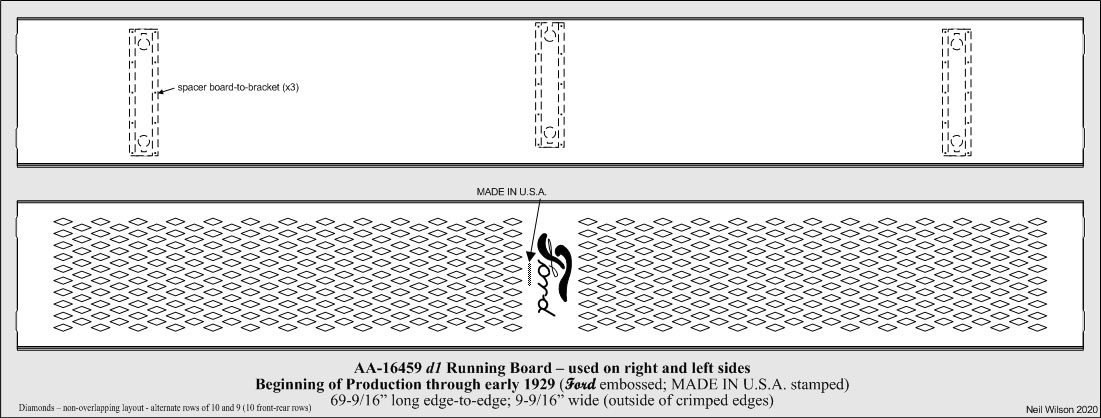
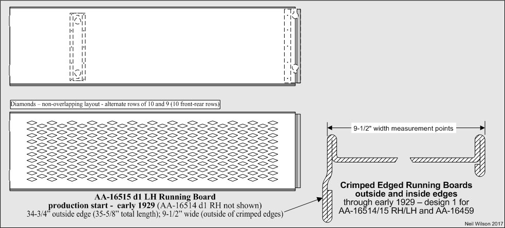
- AA-16459 d1 – long running board with crimped inner/outer edges (used on both sides of the AA)
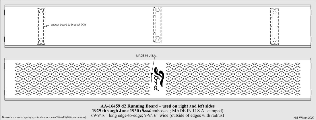
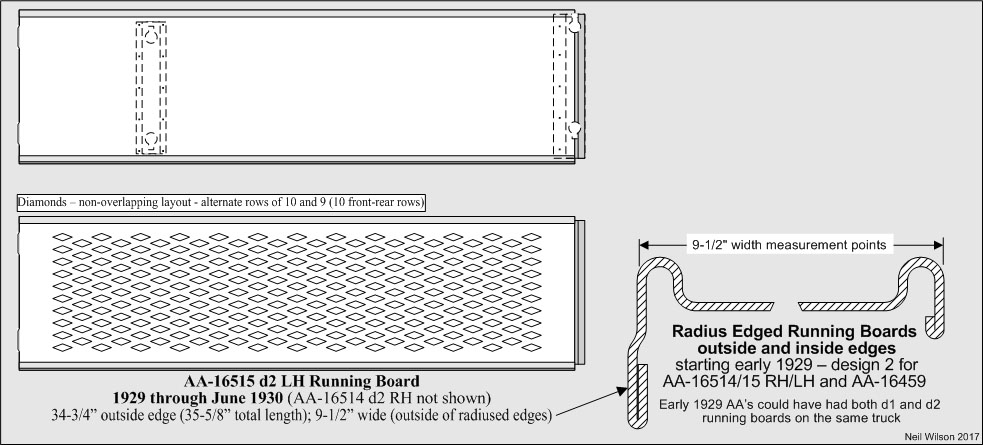
- AA-16459 d2 – long running board with radius inner/outer edges (used on both sides of the AA)
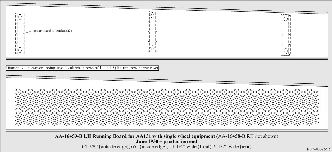
- AA-16458-B/59-B – long, right/left hand running boards for AA131 with single wheel equipment
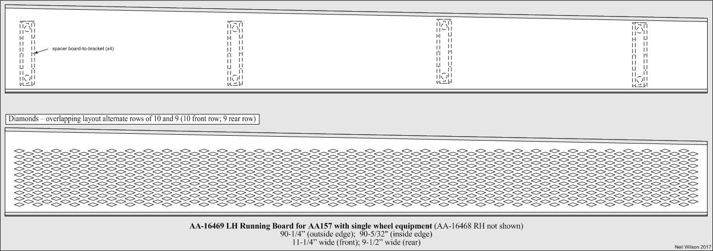
- AA-16468/69 – long, right/left hand running boards for AA157 with single wheel equipment
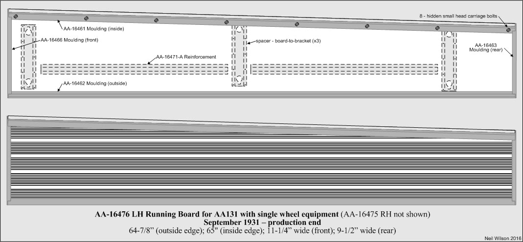
- AA-16475/76 – long, right/left hand running boards for AA131 with single wheel equipment (linoleum covers)
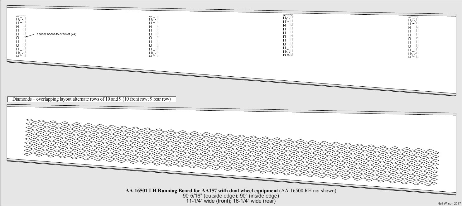
- AA-16500/01 – long, right/left hand running boards for AA157 with dual wheel equipment
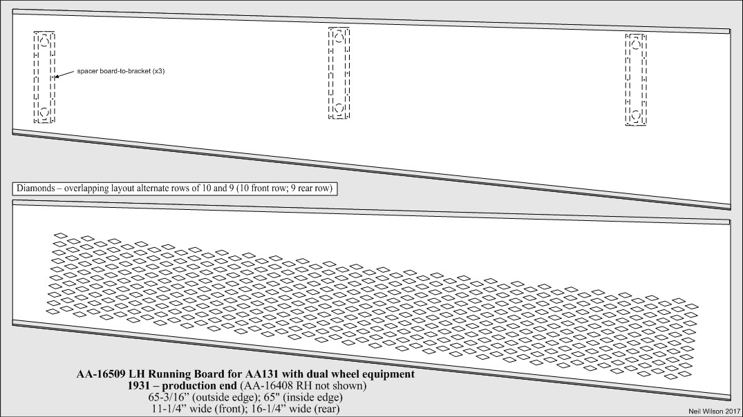
- AA-16508/09 – long, right/left hand running boards for AA131 with dual wheel equipment
- AA-16514/15 d1 – short, right/left hand running boards with crimped inner/outer edges
- AA-16514/15 d2 – short, right/left hand running boards with radius inner/outer edges
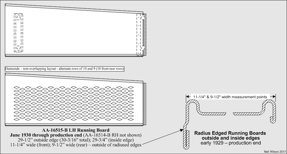
- AA-16514-B/15-B – short, right/left hand running boards
Gallery (Running Board Drawings)
Alignment (Running Board to Fender)
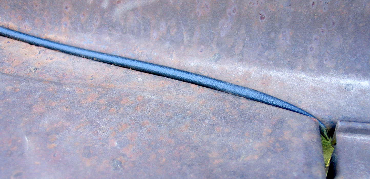
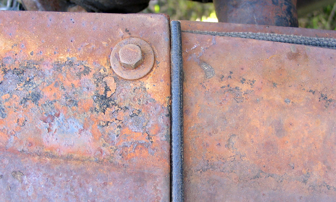
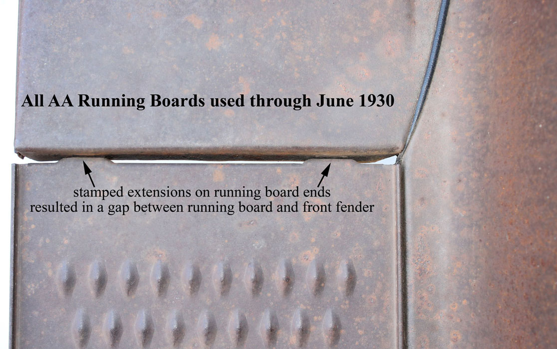
For 12/27—6/30, AA running boards were designed to have a slight gap between the running board and fender. This was because of extension stampings on the ends at each bolt hole location. See the alignment gallery.
Starting in 6/30 (with 76-B, 82-B, and 85-B) the extensions were eliminated and the running boards butt flat against fenders.
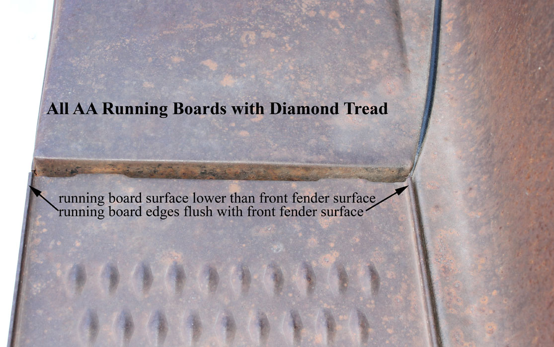
When installed, the diamond embossed surface of the AA running boards were lower than the surface of the fender.
The inside and outside edges of the running boards were flush with the top surface of the front fenders as shown in the alignment gallery.
Galley (Running Board to Fender Alignment)
Spacers (Running Board)
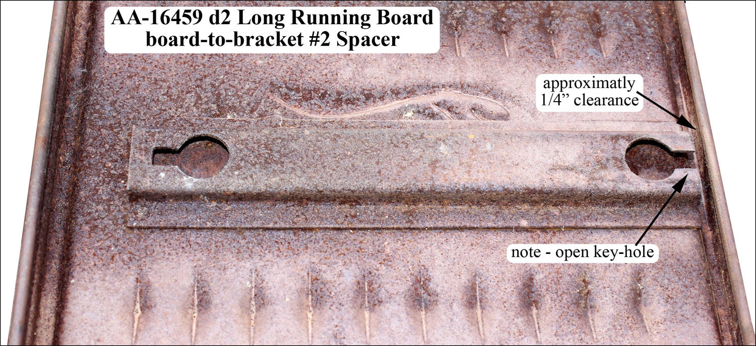
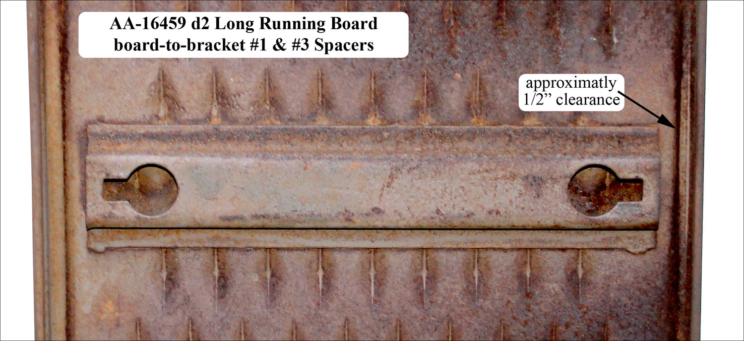
The running board undersides had stamped spacers spot welded in place. These spacers were the same style as for the A-chassis running boards. The spot welds were many times visible on the running board topside after painting. Each spacer had two key-hole shaped openings for running board to bracket special head carriage bolts.
AA131 long running boards had three spacers. Four spacers were used for AA157 long running boards. The spacers gallery shows examples of the spacers for A-16459 d2 running board. Note that the #2 spacer had an inside open key-hole shape.
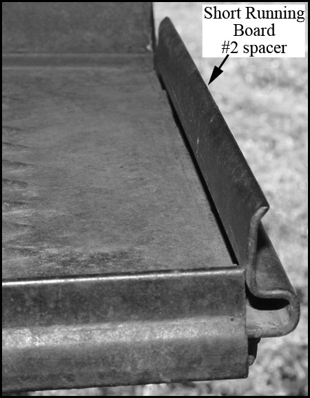
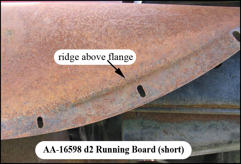
Short running boards had two spacers with the #2 (i.e. rear) spacer extending above the rear edge of the running board. For strength, this #2 spacer was stamped of approximately 3/32″ (.1″) thick metal.
The AA-16515 d1 short running board photograph in the spacers gallery shows this #2 rear spacer. The same type of spacer was used for the other short AA running boards (AA-16515 d2 and AA-16514-B/15-B).
Also see drawings gallery for more running board spacer information.
Gallery (Running Board Spacers)
Reinforcements (Running Board)
The linoleum covered AA-16475/76 running boards had two flanged, U-shaped reinforcements that were spot-welded to the underside. These reinforcements ran lengthwise 3-1/2″ from the outer lip.
They were separated by the #2 (center) spacer. A top view of these reinforcements are shown in the drawings gallery.
Fasteners (Running Board)
Running boards were fastened to the running board brackets with special headed 5/16-18 carriage bolts, hex nuts and lock washers. The RGJS specifies a raven finish for these fasteners.
Note – trying to use the Ford Parts Price List booklets to determine finish just leads to confusion due to some mistakes in the booklets.
The witches-hat-style, special head carriage bolt had a head that fit snugly into the keyhole openings of the running board spacers which were spot-welded to the underside of the running board.
The bolt lengths changed with the conversion from forged to stamped running board brackets. The bolt threads did not extend beyond the nut by more than 1/4″.
Finish (Running Board)
AA running boards with an embossed diamond tread were dipped, gloss, black enamel finished.
Running boards AA-16475/76 (RH/LH) were linoleum covered with trim on all four edges (refer to the drawings gallery). The bottom sides were gloss, black enamel finished. The engineering drawing suggests that the, most likely black, linoleum covers were a broken, ribbed pattern running the length of the running board with ribs parallel to the outside edge. There was a repeated pattern of eight ribs followed by a plain section (about 1/2″) from outside to inside edges. The trim parts were most likely Zink moldings as follows:
- AA-16461 inside trim – placed along the outside edge of the inside edge radius. Attached through the running board with eight small-headed carriage bolts, hex nuts, and locks. The carriage bolts slid into the channel of the trim. The carriage bolts could not be seen from the top side.
- AA-16462 outside trim – crimped around the bottom edge of the outside edge.
- AA-16463 rear trim – Upside down “L” shaped trim riveted to the running board rear end flange with two rivets (head faced to the inside of the running board end flange).
- AA-16466 front trim – Upside down “L” shaped trim riveted to the running board front end flange with two rivets (head faced to the inside of the running board front flange).
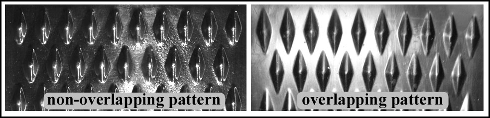
Diamond Tread Layout (Running Board)
The diamond tread was made up of alternating counts of 10 and 9 diamonds across the width (outside to inside). The layouts photo shows the two layouts (non-overlapping and overlapping) for AA running boards. The overlapping layout diamonds had a sharper definition as compared to the non-overlapping layout.
The drawings gallery provides the pattern type, starting-and-ending diamond count, and the basic location of the embossed diamond tread for each running board.
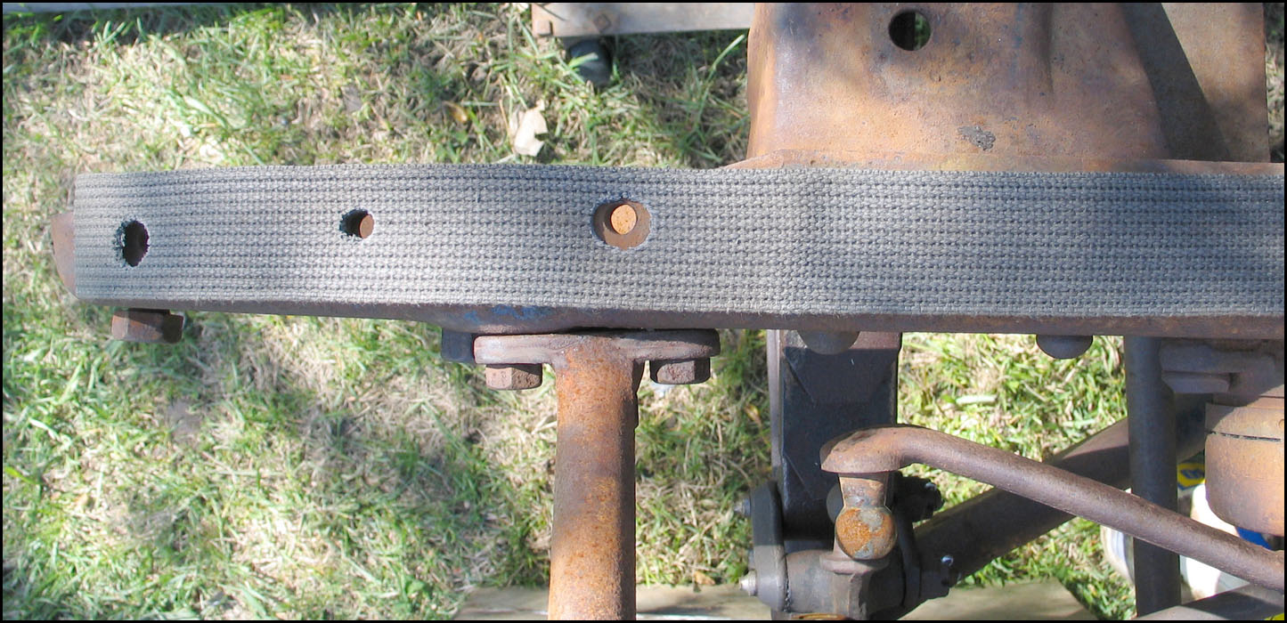
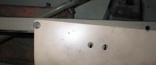
Anti-Squeak (Running Board)
For the AA’s, a strip of fabric friction tape was used between the running board and shield.
Shields (Running Board)
General Information (Running Board Shields)
All shields were a dipped, gloss, black enamel finish.
Shields were referred to as short or long. Short shields were those with part numbers 16598 and 16599.
All other running board shields were long and were used in conjunction with long running boards and rear fenders.
Fasteners (Running Board Shields)
The top-front of a running board shield was under the front fender. The front fender bolt at the rear of the on-frame fender flange held both the fender and shield.
The remainder of a running board shield was bolted to one or more AA-5110 frame brackets attached to the upper outside face of the frame side members.
The initial design short shields are the exception (no frame brackets used). Refer to AA-16598/99 d1.
The number of frame brackets which were installed on a given frame depended on the type of shield being used (short shield or long shield). There were three designs/usage-dates for these brackets.
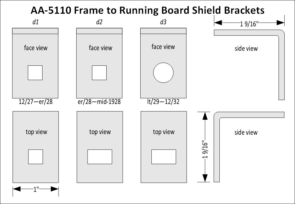
AA-5110 Bracket Usage Per Side
Short Running Boards Shields AA-16598/99 (RH/LH):
- d1 – no brackets used
- d2 – two brackets
Short Running Boards Shields AA-16598-B/99-B (RH/LH):
- two brackets
Long Running Board Shields
- AA131 – four brackets*
- AA157 – five brackets*
*Note that AA’s with long running board shields and frame mounted side wheel carriers did not have the bracket installed above the carrier support bracket
d1—d2 Bracket Fasteners:
- A-20556 – 1/4-20 x 3/4 carriage bolt (9/16 head)
- A-21664 – 1/4-20 (1/4 x 1/2) carriage nut RF
- A-22165 – 1/4 (1/16 x 35/64) lock washer (cad.)
d3 Fasteners – to frame:
- A-????? – 5/16 x ?/? round head rivet (9/16 head)
d3 Fasteners – to splash shield:
- A-20556 – 1/4-20 x 3/4 carriage bolt (9/16 head)
- A-21664 – 1/4-20 (1/4 x 1/2) carriage nut RF
- A-22165 – 1/4 (1/16 x 35/64) lock washer (cad.)
By Part# (Running Board Shields)
Descriptions of the ten running board shields are found below by part number (in numerical sequence).
A given body type’s running board shield part ids are found in the parts links table. This provides direct links to running board shields for a body type.
AA-16534 RH Shield (Long)
A 1931 right hand long shield was used on AA131‘s with a long running board and had either a left front fender wheel carrier or an under body carrier. Consequently, the shield did not have a hole in the side for a side wheel carrier support and grommet. Shield AA-16536-B was the left hand long shield used in conjunction with this shield.
AA-16535 RH Shield (Long)
A right hand long shield was used from 12/27—6/30 on AA131‘s with long running boards and no frame mounted side wheel carrier. Shield AA-16536 was the left hand long shield used in conjunction with this shield. The vertical face was slightly convex. However, the shield to front fender flange was flat resulting in a slight ridge. This ridge is shown under AA-16589 d2 in the shields gallery. There were two designs of AA-16535 as follows (applies to AA-16536 also):
- d1 – 12/27—7/28. The shield had two half-moon cutouts on the top inner edge for the installation of two U-bolts or two floor tie straps. This applied to the 88-A Platform and 89-A Express that used body stops through 7/28. Body stops are part of the AA-chassis, AA-5000 Frame parts group.
- d2– Beginning in August 1928, the front half-moon cutout was eliminated. Consequently, there was one half-moon cutout for the installation of one U-bolt or one floor tie strap. This applied to the 88-A Platform and 89-A Express which used “L” brackets for the front mounting point beginning in August 1928. Frame “L” brackets are part of the AA-chassis, AA-5000 Frame parts group. There was a bolt hole added to this shield to allow the frame and cargo body “L” brackets to be bolted together.
AA-16535-B RH Shield (Long)
A right hand long shield was used beginning 6/30 on AA131‘s with long running boards that had a side wheel carrier. The shield had a hole in the side for a side wheel carrier support and grommet. Shield AA-16536-B was the left hand long shield use in conjunction with this shield.
AA-16536 LH Shield (Long)
A left hand long shield was used from 12/27—6/30 on AA131‘s with long running boards. Either shield AA-16535 or AA-16538 was the right hand long shield used in conjunction with this shield. The vertical face was slightly convex. However, the shield to front fender flange was flat resulting in a slight ridge. This ridge is shown under AA-16589 d2 in the in the shields gallery. There were two designs of this AA-16536 shield as follows (applies to AA-16535/38 also):
- d1 – 12/27—7/28. The shield had two half-moon cutouts on the top inner edge for the installation of two U-bolts or two floor tie straps. This applied to the 88-A Platform and 89-A Express which used body stops through July 1928. Body stops are part of the AA-chassis, AA-5000 Frame parts group.
- d2 – Beginning in August 1928, the front half-moon cutout was eliminated. Consequently, there was one half-moon cutout for the installation of one U-bolt or one floor tie strap. This applied to the 88-A Platform and 89-A Express which used “L” brackets for the front mounting point beginning in August 1928. Frame “L” brackets are part of the AA-chassis, AA-5000 Frame parts group. There was a bolt hole added to this shield to allow the frame and cargo body “L” brackets to be bolted together.
AA-16536-B LH Shield (Long)
A left hand long shield was used beginning in 6/30 for the 85-B Panel Delivery and 89-A Express. It was also used for 1931 AA131‘s with long running boards. Either shield AA-16535-B or shield AA-16534 were the right hand long shields use in conjunction with this shield.
AA-16538 RH Shield (Long)
A right hand long shield was used 8/28—6/30 on AA131‘s with long running boards and a frame mounted side wheel carrier. The shield had a hole in the side for a side wheel carrier support and grommet which applied to the 85-A Panel Delivery and 89-A Express.
Shield AA-16536 was the left hand long shield used in conjunction with this shield. The vertical face was slightly convex. However, the shield to front fender flange was flat resulting in a slight ridge as shown in the shields gallery.
AA-16585/86 (RH/LH) Shield (Long)
These right and left hand long shields were used on the AA157‘s with long running boards.
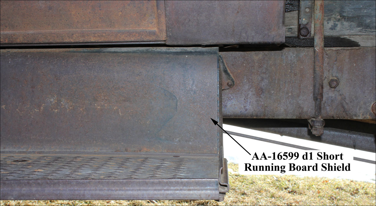
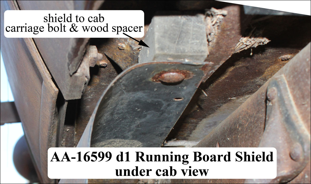
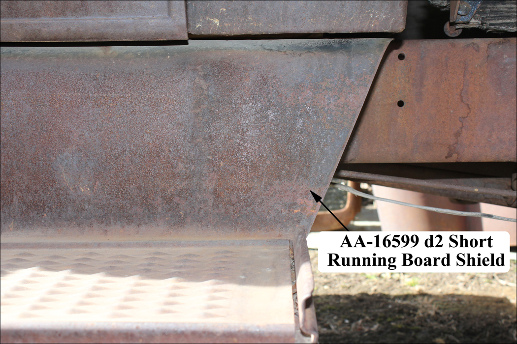
AA-16598/99 (RH/LH) Shields (Short)
These short shields were used from 12/27—6/30 for AA’s with the 76-A Open Cab and 82-A Closed Cab without rear fenders. There were two designs as follows:
- d1 – Short shields used through late 1928 were squared off with the rear of the running board. The top side of each shield was tapered. The shield narrower rear end was bolted to the underside of the cab side sills with a wood spacer between the shield and cab side sills. The vertical face of these shields was flat. Refer to the shields gallery.
- d2 – Short shields used beginning in late 1928 were angled from the rear of the running board up to the cab. The top side of the shields was straight with the frame beginning at the frame body bracket rearward (i.e. not tapered). The vertical face was slightly convex. However, the shield to front fender flange continued to be flat resulting in a slight ridge as shown in the shields gallery.
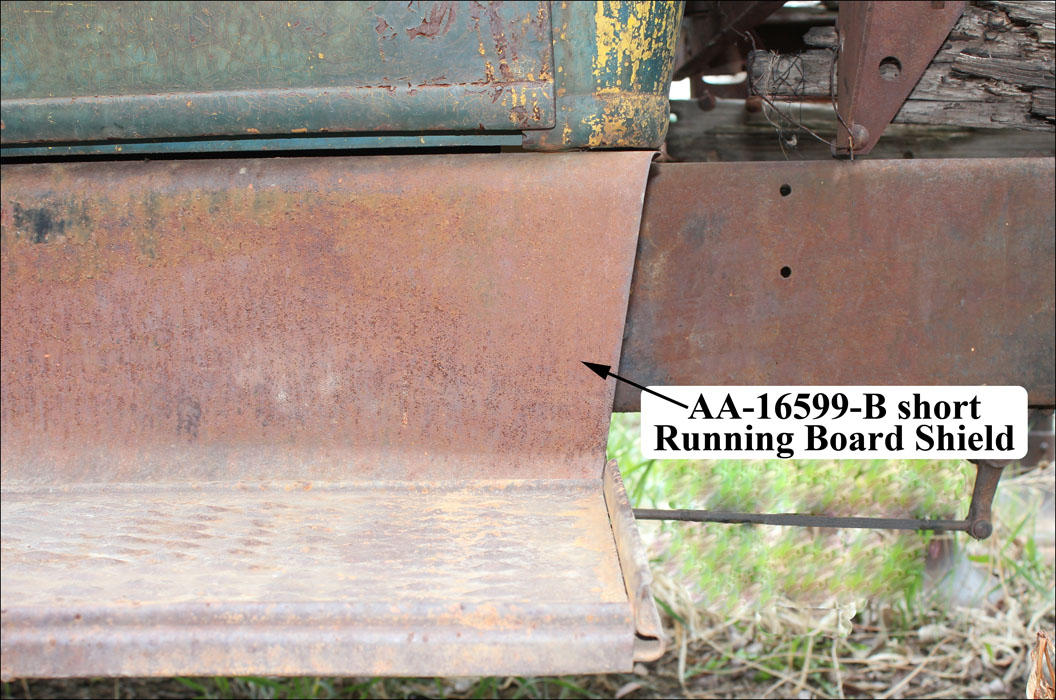
AA-16598-B/99-B (RH/LH) Shields (Short)
These short shields were used with short running boards beginning in June 1930 for AA’s with the 76-B Open Cab and 82-B Closed Cab without rear fenders. In addition, the 199-A Ice Wagon and 242-A Heavy Duty Express were the only two open cargo bodies which were equipped with rear fenders but use the short shields and running boards.
These shields had 90° flanges at the front for bolting to the corresponding flanges of the front fender shields. The rear edges of these shields had a slight angle from the running board up to the back of the cab as shown in the shields gallery.
Gallery (Running Board Shields)
Anti-Squeak (Running Board Shields) – a.k.a on-frame webbing
Running board shields rested on the frame forward of the frame cab & close-body bracket.
Only this portion of the running board shields had on-frame anti-squeak.
Shields (Front Splash)
By Part# (Front Splash Shields)
AA’s used A-chassis front splash shields A-16527 (d1—d3) and A-16527-B. These shields were dipped gloss black enamel finished. The three surfaces of original shields were slightly convex (i.e. no flat surfaces).
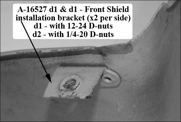
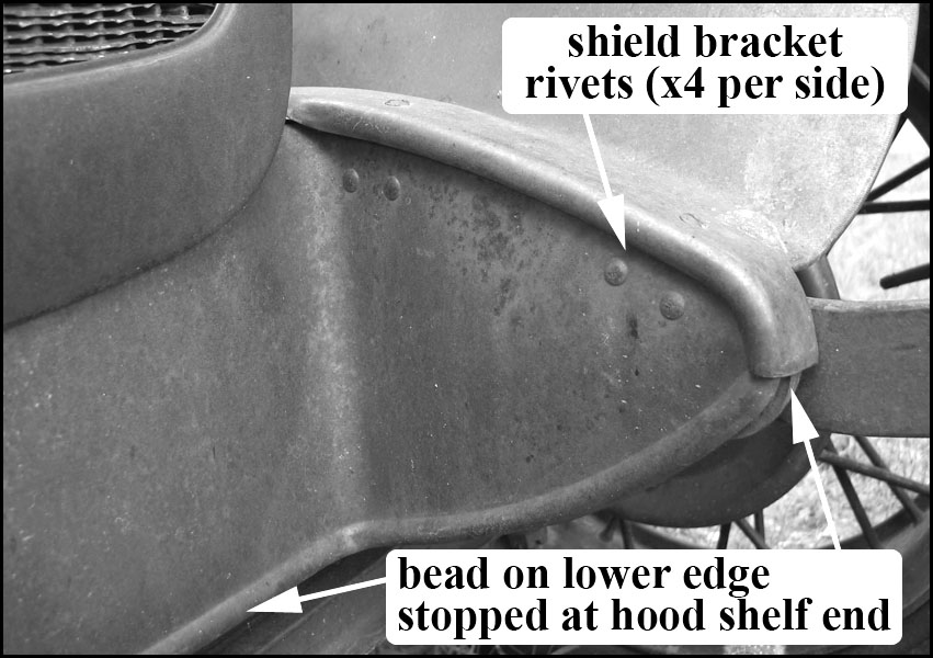
Shield A-16527 – This shield had two installation brackets attached to each side with two rivets/bracket (see the front splash shields gallery). Each bracket extending under the upper flange of the frame side member. Each bracket had a D-nut to accept a hood shelf screw which clamped the shield to the frame.
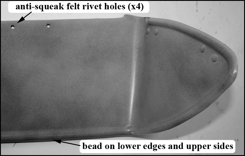
Fit between the shield and radiator shell, there were two felt anti-squeak pads attached to the shield’s top-front edge (attached with two black enamel tubular rivets per pad). There were three designs of this shield:
- Shield A-16527 d1 – had 12-24 D-nuts; used through July 1928; had a reinforcement bead along the lower edges only (i.e. no bead at the top edges).
- Shield A-16527 d2 – had 1/4-20 D-nuts; used July—December 1928; also had a reinforcement bead along the lower edges only (i.e. no bead at the top edges).
- Shield A-16527 d3 – had 1/4-20 D-nuts; used 1/29—6/30; had a continuous reinforcement bead along the top-side edges and along the lower edges.
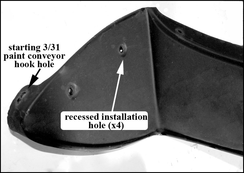
Shield A-16527-B – Extended approximately 2″ past the frame to meet with the front fenders. Fit between the shield and radiator shell, there was a felt anti-squeak pad attached to the shield’s center-top-front edge with two black enamel tubular rivets. This shield had recessed installation holes for attaching the shield to the front bumper arm mounting studs (two per side).
Fasteners were 1/4-28 round head screws and lock washers (black enamel finish). The forward fender fastener clamped the fender and shield together. Starting in March 1931, the right hand top flange was extended rearward. The extension had a 5/8″ punched hole for a paint conveyor hook.
Refer to the front splash shields gallery photo.
Gallery (Front Splash Shields)