2024/01/11 update
Page Contents
*************Tap/Click*************
This page provides information about
brackets, stops, supports, and spacers
listed in the frame parts group
Battery Support to Frame Bracket
This bracket was part AA-5105 and had two designs. It was riveted to the inside of the left frame side member for the installation of the battery support assembly. Consequently, the battery support assembly was located at the same location (relative to the top of the frame) as for the A-chassis.
Bracket AA-5105 d1 was used through August 1928. It had two holes for installation of the battery support assembly with integral forged mounting brackets. AA-5105 d2 had one hole for installation of the battery support assembly with a stamped strap. It was used starting September 1928.
images to be added here when available
Body Stops
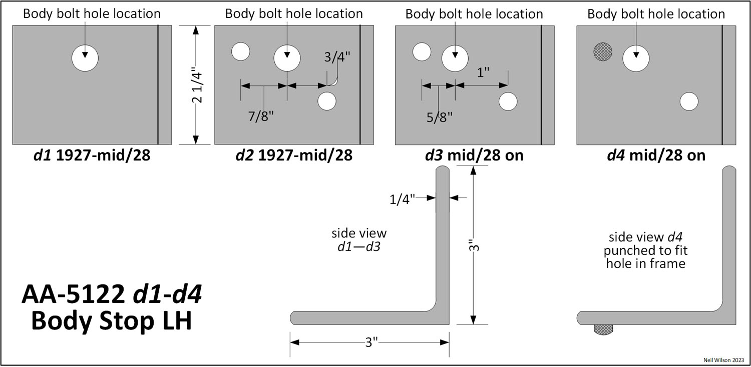
AA-5121/22 (RH/LH) frame body stops were used for the installation of both the 88-A platform and 98-A express bodies. They are also seen in Ford archive AA-chassis photos. So, they may have been installed on all AA-chassis.
As shown in the body stop images, there were four designs (d1—d4). The d1 stops were attached to the frame with the rear cab body bolt only. The d2 stops were attached to the frame with two bolts. In mid-1928 the location of the rear body bolt was moved forward 1/4” for the AA-frame and 82-A closed cab. This resulted in the d3 body stops being created. The d4 body stops had the forward bolt hole simply punched with an upset to fit the hole in the frame.
| Body Stop Parts | ||
|---|---|---|
| # | Part | Part Description |
| Neil Wilson 2023 | ||
| 12/27—7/28 | ||
| 1 | AA- 5121 | Stop (frame body) RH – d1–d4 |
| 1 | AA- 5122 | Stop (frame body) LH – d1–d4 |
| Standard Parts – Stop to frame – attachment | ||
| 4 | A-20764 | 5/16-18 x 7/8 (1/4 x 1/2) hex head bolt |
| 4 | A-21707 | 5/16-18 (1/4 x 1/2) hex nut (raven finish) |
| 4 | A-22217 | 5/16 (1/16 x 37/64) lock washer (raven finish) |
Note the overlapping usage dates for the different designs indicated in the body stop images.
Made of 1/4″ thick 3” x 3″ angle iron, body stops were 2-1/4” wide and bolted to the top of the frame side members at the rear of the cab.
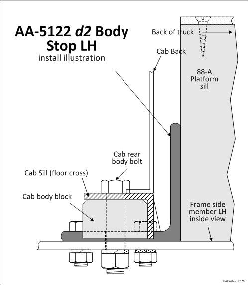
The cab’s rear floor cross sill (AA-82055) was designed to set over the foot of the body stop.
The cab’s rear body bolts ran through the stops requiring the cab’s rear body blocks to be notched to fit over the stops and bolt heads. The stops extended up behind the cab preventing the platform or express body from moving forward. The body stop images shows a detailed installation.
Body Stop Images
Cab & Close-Body Bracket
| Cab/Closed-Body Bracket Parts | ||
|---|---|---|
| # | Part | Part Description |
| Neil Wilson 2023 | ||
| All production | ||
| 1 | A-5075 | Body Bracket – on frame – front |
| Standard Parts – Bracket to frame – attachment | ||
| 3 | A-23375 | 5/16 x 3/4 round head rivet |
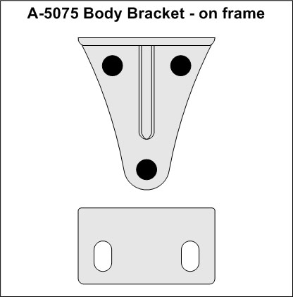
This was an A-chassis bracket riveted to the frame assembly. Its official Ford name was body bracket – on frame – front. The AA-5075-image illustrates this bracket. It was installed below the hinge pillar where two carriage body bolts were installed.
These brackets were forged steel initially. This was changed to stamped steel in early 1929. These brackets were riveted-to-and-finished-with the frame. Pieces of anti-squeak were put on the brackets to make to make a level surface with the on-frame anti-squeak.
Cargo-Frame Bracket
| Cargo-Frame Bracket Parts | ||
|---|---|---|
| # | Part | Part Description |
| Neil Wilson 2023 | ||
| 8/28—12/32 | ||
| 2 | AA- 5077 | Bracket (frame) to body sill bracket |
| Standard Parts – Bracket to frame | ||
| 4 | A-????? | 5/16 x ?? round head rivet |
| 2 | AA-88084 | Bracket (body sill ) to frame bracket |
| Standard Parts – Bracket to sill – attachment | ||
| 4 | 3/8-24 x 2-3/4 (9/32 x 9/16) hex head bolt | |
| 4 | 3/8-24 (5/16 x 9/16) hex nut (chamfered 1 side) | |
| 4 | 3/8 (1/16 x 1) flat washer | |
| 4 | 3/8 (3/32 x 21/32) lock washer | |
| Standard Parts – Bracket to bracket – attachment | ||
| 2 | A-21237 | 1/2-20 x 1-1/2 (3/8 x 3/4) hex head bolt |
| 2 | A-21845 | 1/2-20 (7/16 x 3/4) hex nut |
| 2 | A-22330 | 1/2 (1/8 x 7/8) lock washer |
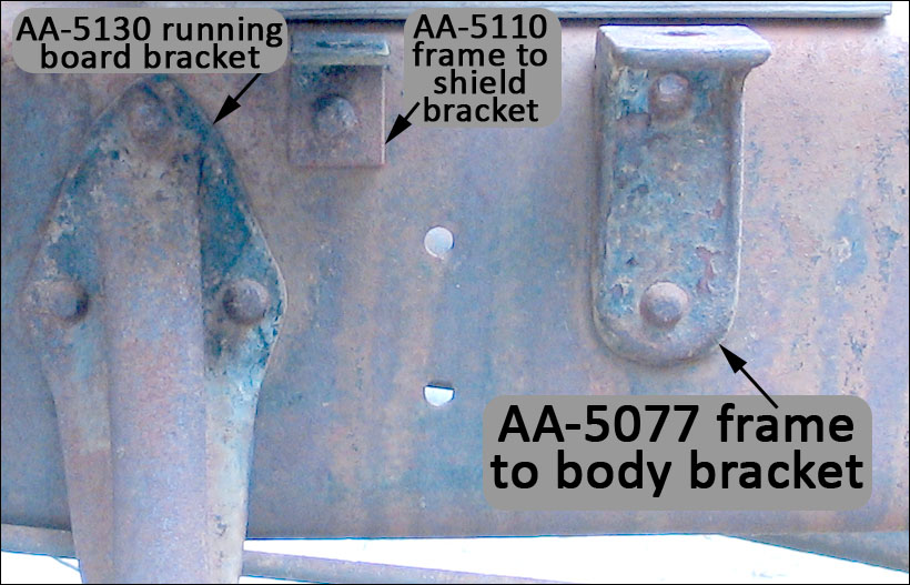
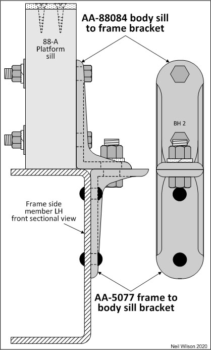
AA-5077 frame to body sill bracket was introduced in August of 1928 and was used in combination with AA-88084 body sill to frame bracket. These brackets replaced both the AA-5121/22 body stops as well as the 88-A platform front U-bolts and 89-A express front floor tie straps.
The images show that part AA-5077 was installed on the outer face of the frame side members with two rivets. The AA-88084 bracket was bolted to the outer face of the 88-A platform sills or 89-A express sills. When the cargo body was mounted on the frame, the brackets were bolted together.
Finish – AA-5077 frame to body sill bracket was riveted-to-and-finished-with the frame (chassis black). AA-88084 body sill to frame bracket as installed-to-and-finished-with the body (in body color).
These frame and sill brackets were used as other body types were introduced. They were used for the installation of the following body types:
- 88-A, 185-A, 185-B, and 187-A platform
- 89-A express
- 239-A express – meat packers
- 242-A express – heavy duty
- 244-A and 248-A grain
The 229-A service body use the frame brackets only (with floor body bolts).
Other body types used floor body bolts installed directly through the frame top flange.
These forged steel brackets were replaced with a stamped steel design at some point in 1931.
Cross Member #2 Support Bracket
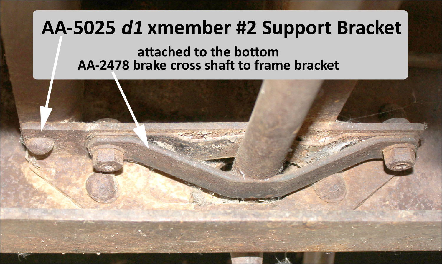
This bracket was riveted to the inside of each frame side member. These supports were use through early 1929 for those AA’s with the AA-5025 d1, inverted “U” style, #2 cross member. These brackets resulted in holding the #2 cross member at the same location (relative to the top of the frame) as the A-chassis.
AA-5073 was used through February 1928. AA-5073-B was used starting March 1928. The difference in these two parts need to be investigated.
Engine Rear Support Assemblies
The following covers the three AA engine rear support assemblies used for the AA-chassis.
Ford included the supports for the rear of the engine under the frame parts group. This was because the first support brackets were riveted to the frame. The replacement support assemblies (released sometime in December 1927) were bolted to the frame and continued to be listed under the frame parts group.
When the engine front support assembly was introduced in late 1928, it was placed in the engine parts group also.
Support Bracket to Flywheel Housing – Each engine support assemblies used unfinished 1/2-13 x 1-5/8 hex head bolts (with drilled heads) and lock washers. These bolts were safety wired in various ways with 18-gauge wire (plain or raven finished).
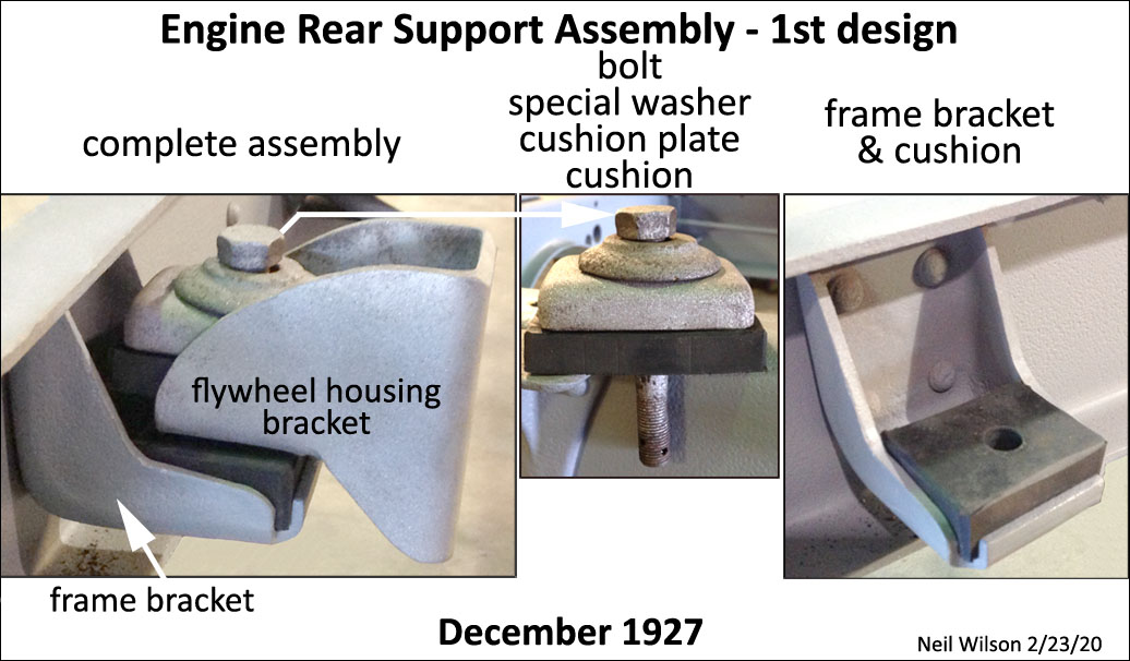
1st Engine Rear Support Assembly
The 1st engine rear support assembly was used in December 1927 (see image below). It consisted of a frame bracket which was riveted to the inside of the frame side member with four rivets. It held a thick cushion. Another bracket was bolted to the flywheel housing and had an extension which rested on top of the cushion. The two brackets and cushion were held together with a bolt, special thick washer, thick metal cushion plate, castle nut, and cotter pin.
This support setup was for both sides and was also used for the A-chassis.
Assembly Finish – The frame bracket was attached before the frame was dip-painted Japan black. The flywheel housing bracket, special thick washer and thick metal cushion plate were most likely painted chassis black. The bolt, castle nut, and cotter pin were most likely unfinished.
2nd/3rd Engine Rear Support Assemblies
The 2nd/3rd engine rear support assemblies were use from 1927—1932.
An assembly included the right or left frame-to-engine support bracket (see image below), A-chassis A-5092 inner and A-5094 outer cushions, and A-chassis A-5095 plate. Assembly fasteners included three 5/16-24 hex bolts, AA-5093 support-to-frame tubular spacers (19/32″ long), castle nuts, and cotter pins.
These parts were assembled with the cushions next to the inside/outside of the frame side member, the support bracket next to the inside cushion, and the plate on the outside of the outside cushion.
The AA-frame side member was thicker than the A-frame side member. Consequently, the three support-to-frame bolts were longer and the AA-5093 support spacers were slightly long than the corresponding A-chassis parts.
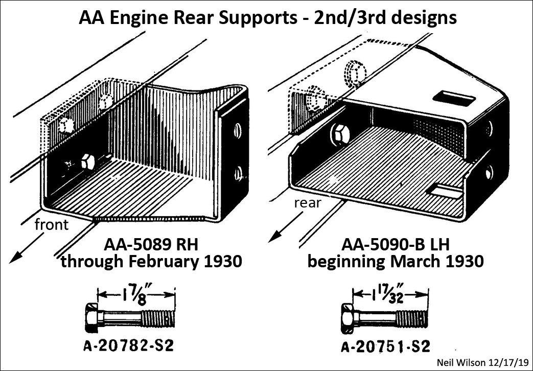
2nd Support Assemblies – used from 12/27—2/30. These support brackets were AA-5089/90 (RH/LH). The open side of the support faced the front of the truck. During use, this support was frequently cracked at the corner of the rear/engine faces.
3rd Support Assemblies – used starting 3/30—12/32. These support brackets were AA-5089/90-B (RH/LH). The open side of the support faced the rear of the truck.
Assembly Finish – The support bracket and support plate were dipped gloss black enamel. The support-to-frame bolts and castle nuts were unfinished through mid-1928 and raven finished starting late 1928. Cotter pins were unfinished.
Cushions – A-chassis parts A-5092 (inner) and A-5094 (outer) were rubber pads (3/16″ thick; 7/32″ thick starting 2/29). The inner cushion was “L” shaped and fit the bottom/side of the support bracket.
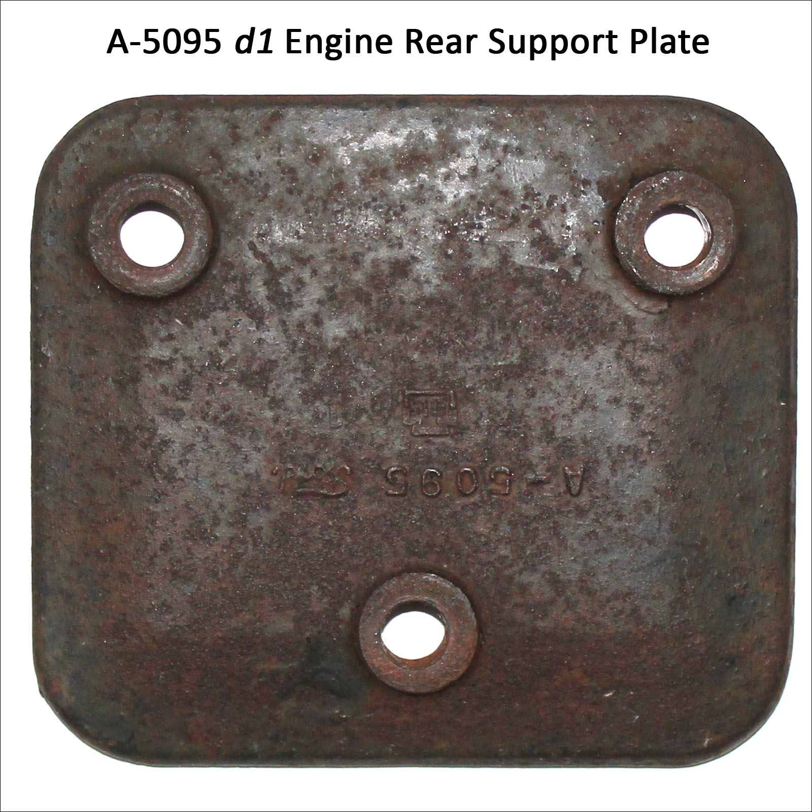
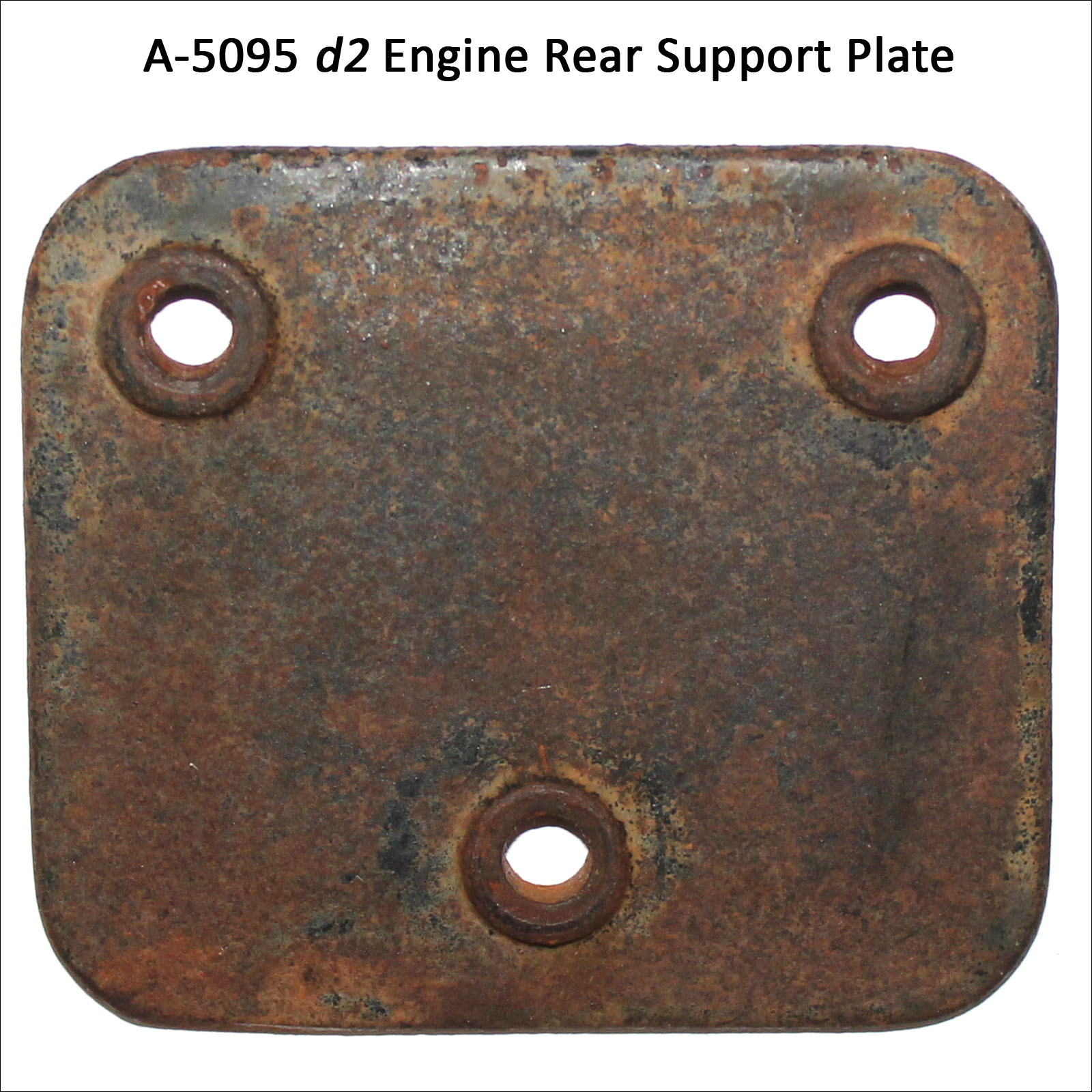
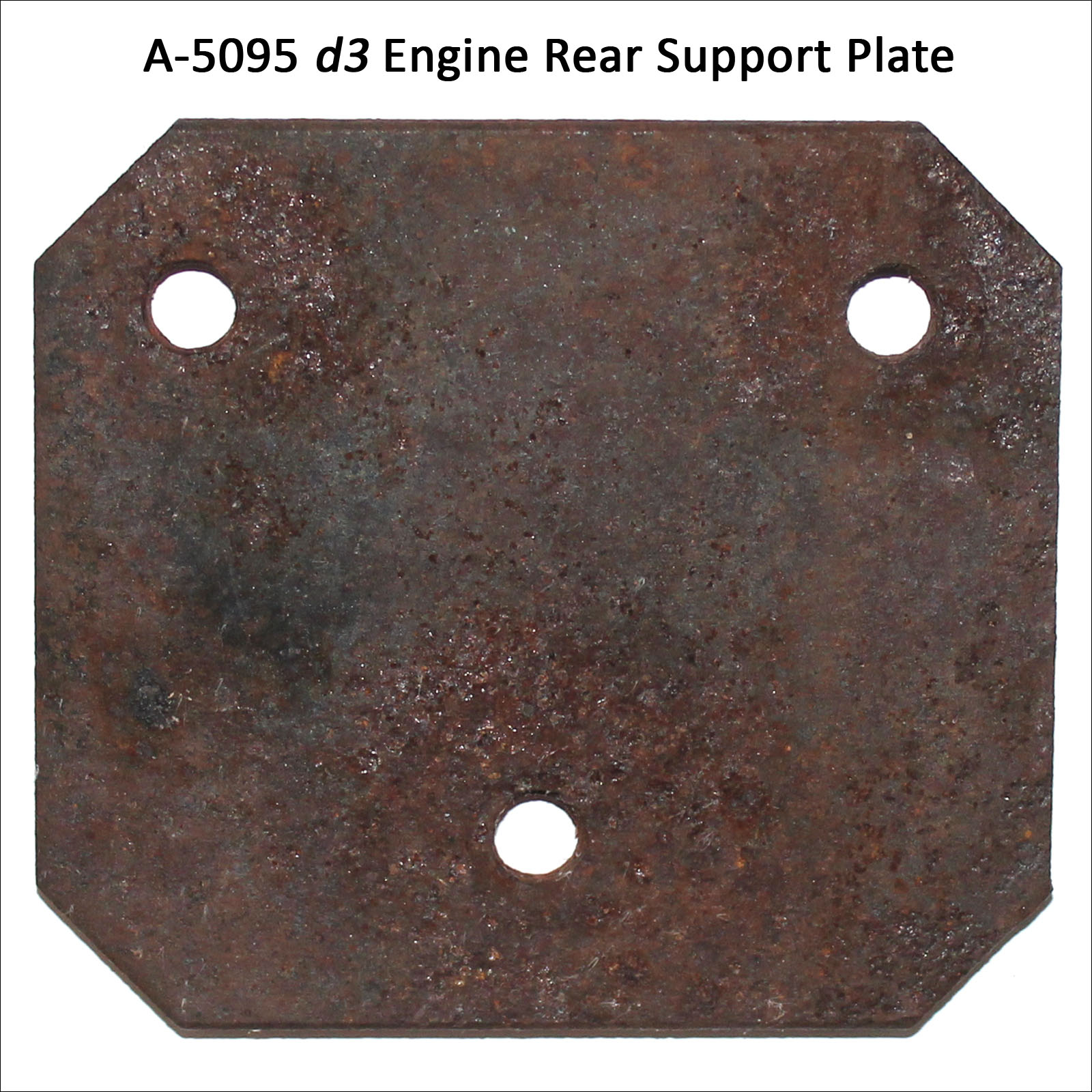
Plate A-5095 – This A-chassis plate had three designs (see the plate gallery):
d1 plate – forged and used through late 1928. Some had “A-5095 Ford” plus manufacture’s trade mark embossed on the face.
d2 plate – malleable casting and used starting late 1928 through February 1930. Some had A-5095 cast on the inside face.
d3 plate – stamped steel with clipped corners and used starting 10/29—12/32. Introduced for 2000 vehicles per day and used exclusively starting 3/30.
Gallery – Engine Rear Support Plate
For the 2nd and 3rd support brackets, relative to the bottom flange of the AA frame side members, the frame installation holes were punched in the same location as the A-frame side members. However, the AA right-hand/left-hand support brackets were designed to place the engine at the same location as the A-support bracket relative to the top of the frame.
Don’t use A-chassis support brackets – Note that the A-chassis support bracket could be mistakenly installed in an AA frame. If mistakenly installed, the engine will set about 1/2″ low at the rear. This will cause cab-to-engine alignment problems for a number of parts (choke rod, starter switch rod, rods from the steering column to distributor and accelerator bracket assembly, brake and clutch pedals, gas line to carburetor).
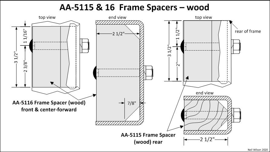
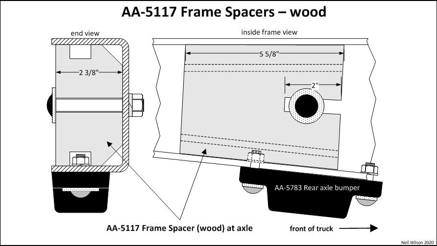
Frame Spacers
Frame spacers were installed on the inside of the frame side members to prevent the compression of the frame when U-bolt or floor tie strap nuts were tightened. There were three styles of spacers (wood-bolt-on, stamped-steel-rivet-on, and stamped-steel-sleeve). Frame spacer styles were converted from wood to rivet-on and then to sleeve.
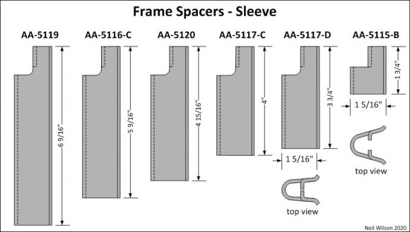
By mid-1929, sleeve style frame spacers were in full production. At that time, this applied to the two open-cargo-body-types in production (88-A platform and 89-A express). All open-cargo-body-types introduced after mid-1929 use sleeve style frame spacers.
Frame spacers style usage was dictated by the frame and body type. Refer to the frame spacer usage table.
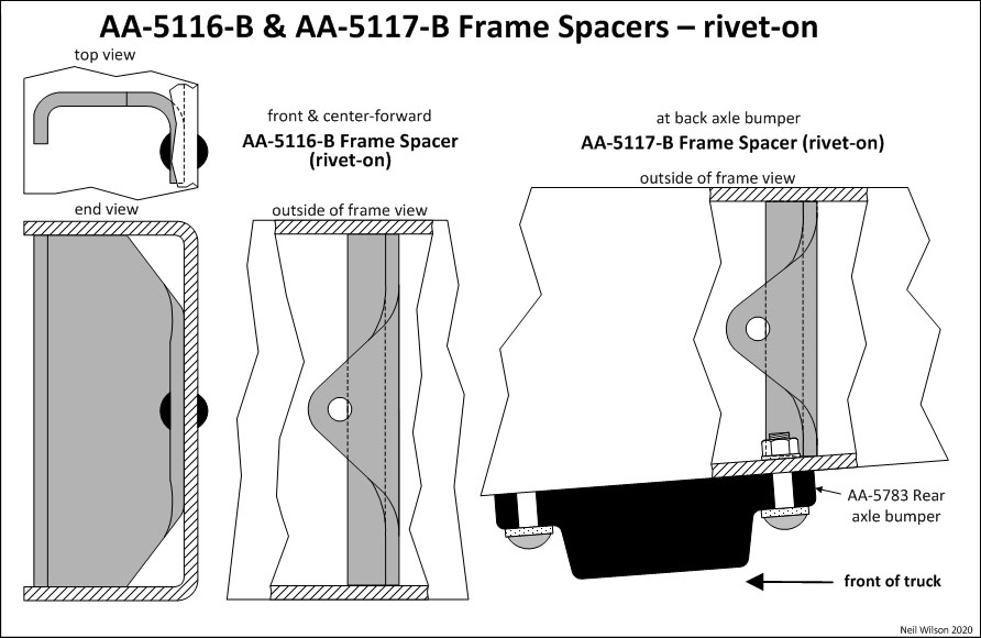
Wood frame spacers were bolted to the frame with one 7/16” carriage bolt for each spacer. Each rivet-on style spacer was attached with one 3/8” rivet. The 7/16” bolt holes punched in frame side members for the wood spacers were reduced in size and slightly moved to accommodate 3/8” rivets. The AA-5005 d2 frame had a mix of wood and rivet-on frame spacers during the conversion.
The AA-5117-B rivet-on spacer was attached to the frame at the back side of the rear axle bumper. This spacer was designed to fit both the right-hand and left-hand frame side members. The sleeve style spacers were held in place by the insertion of the platform inside leg of the U-bolt or the express inside tie strap through the spacer.
Initially, the intermediate sleeve spacer came in right-hand and left-hand versions (AA-5117-C d1 and AA-5118) as per the October 1, 1928 Parts Price List. These spacers were possibly cut at a slight angle across the top face, thus allowing the U-bolt installation to be perpendicular to the bottom of the chassis frame. The AA-5118 LH part number was dropped in the December 1, 1929 Parts Price List. Consequently, modified spacer AA-5117-C d2 became the spacer located at the rear axle bumper on both sides. The actual date of this change is not known.
Gallery – Frame Spacer Drawings
Hood Clip Bracket
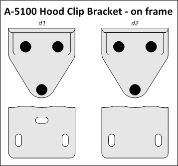
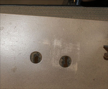
A-5100 hood clip bracket was an A-chassis part used on the AA-chassis. The images below shows the bracket designs.
The d1 bracket had three oval bolt holes on the top surface. The running board shield had corresponding round holes. This design was used into January 1928. The d2 bracket had two oval bolt holes on the top surface and the running board shield was modified accordingly.
Both the d1 and d2 brackets were forged steel. The d2 bracket was changed to stamped steel in early 1929.
Bracket fasteners were (3) A-23377 5/16 x 13/16 button head rivets. These brackets were riveted-to-and-finished-with the frame. Pieces of anti-squeak were put between the brackets and running board shields to make the brackets level with the on-frame anti-squeak.
Initially this part was listed as “Hood shelf support bracket”.
Hood Clip Bracket Images
Running Board Brackets
By Part# – Running Board Bracket
A-5125 – This running board bracket was used on both the A-chassis and AA-chassis as the #1 (front) bracket. It was forged steel through March 1929 and stamped steel starting December 1928. Note the overlapping dates. For strength, reinforcing ribs were stamped on each side of the top rivet hole in June 1931.
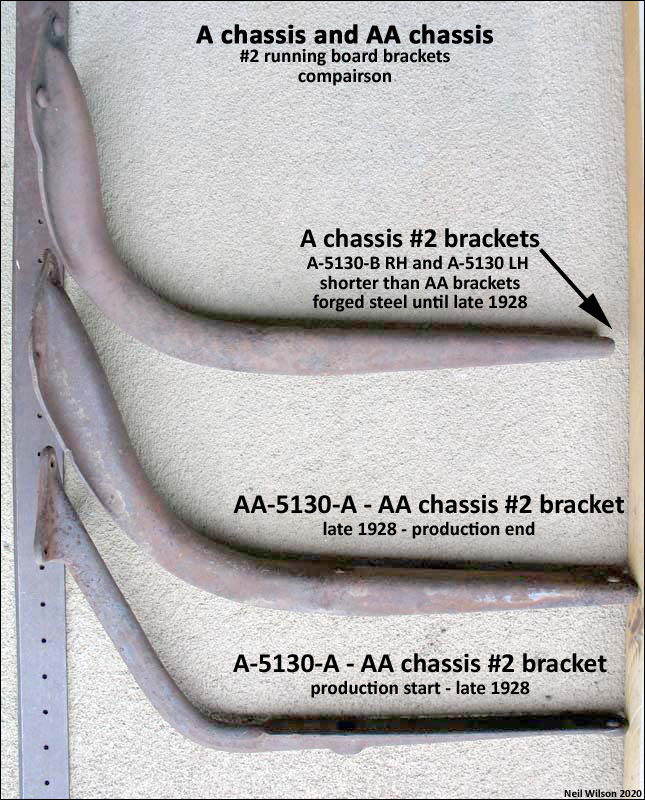
A-5130-A & AA-5130-A – A-5130-A running board bracket was forged steel and was only used on the AA-chassis. This bracket did not carry an AA prefix for reasons unknown. FYI – This incorrect part id is embossed on the bracket. The incorrect prefix was corrected when the bracket was replaced with stamped steel bracket AA-5130-A in late 1928. These were the #2 brackets. For the AA157 with long running boards, this bracket was the #2 and #3 brackets.
Note – The corresponding A-chassis #2 running board brackets (forged or stamped steel) were parts A-5130-B RH and A-5130 LH. These brackets are shorter than the AA brackets.
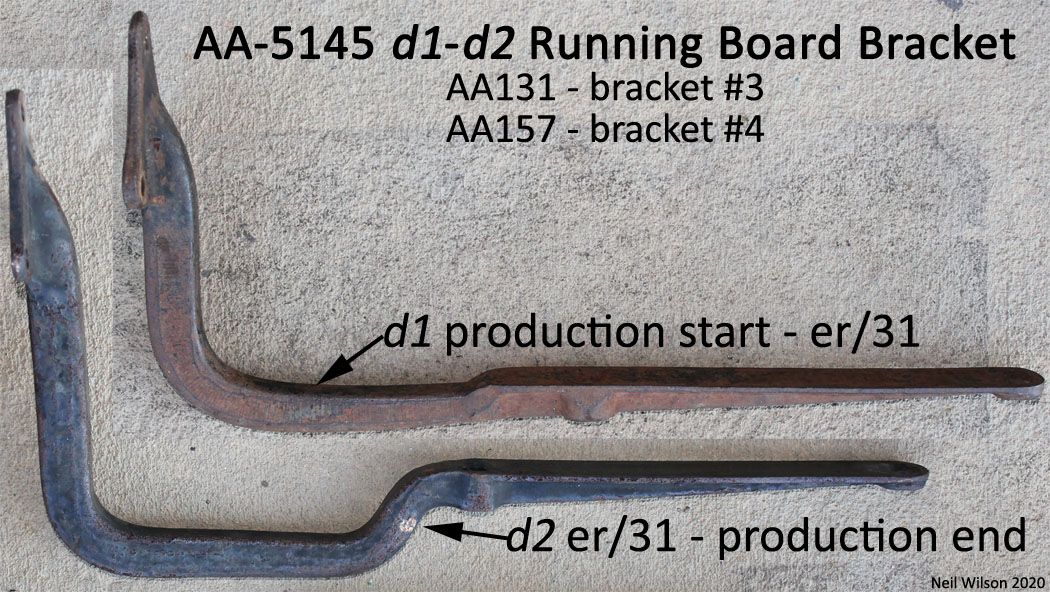
AA-5145 d1–d2 – This running board bracket was forged steel throughout production. It was used for AA’s with long running boards as the rear bracket. This was the #3 bracket for AA131 and the #4 bracket for the AA157. The AA-5145 image shows the d1 and d2 brackets. The d2 bracket was used on all AA’s starting in early 1931. This new design provided clearance for the longer AA-5560-E spring assembly used for a few 1931 AA body types.
Part#s – AA Running Board Bracket
- ..A-5125 #1 running board bracket (forged and stamp steel)
- ..A-5130-A #2 running board bracket (forged steel)
- AA-5130-A #2 running board bracket (stamped steel) + #3 for AA157
- AA-5145 d1–d2 #3 running board bracket (except – #4 for AA157) forged steel
Locations – AA Running Board Bracket
- AA’s with short running boards – had brackets #1 and #2
- AA131 with long running boards – had brackets #1, #2, #3
- AA157 with long running boards – had brackets #1, #2, #3, #4
Fasteners/Finish – Running Board Brackets
Bracket to frame fasteners were 5/16 Button Head Rivets (3 per bracket). Brackets were riveted-to-and-finished-with the frame.
Running Board Shield Brackets
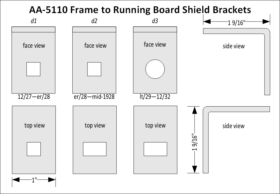
AA-5110 d1-d3 frame-to-running-board shield brackets were attached to the upper outside face of frame side members. The brackets image shows drawings of the bracket designs.
The number of brackets which were installed on a given frame depended on the type of shield being used (short shield or long shield). Note there were three designs and usage dates.
Usage/Frame-Side – Shield Brackets
Short Running Boards Shields AA-16598/99 (RH/LH):
- d1 – no brackets used
- d2 – two brackets
Short Running Boards Shields AA-16598-B/99-B (RH/LH):
- two brackets
Long Running Board Shields
- AA131 – four brackets
- AA157 – five brackets
Note that AA’s with long running board shields and frame mounted side wheel carriers did not have the bracket installed above the carrier support bracket
Fasteners – Shield Brackets
d1–d2 Bracket Fasteners:
- A-20556 – 1/4-20 x 3/4 carriage bolt (9/16 head)
- A-21664 – 1/4-20 (1/4 x 1/2) carriage nut RF
- A-22165 – 1/4 (1/16 x 35/64) lock washer (cad.)
d3 Fasteners – To frame:
- A-????? – 5/16 x ?/? round head rivet (9/16 head)
d3 Fasteners – To splash shield:
- A-20556 – 1/4-20 x 3/4 carriage bolt (9/16 head)
- A-21664 – 1/4-20 (1/4 x 1/2) carriage nut RF
- A-22165 – 1/4 (1/16 x 35/64) lock washer (cad.)