
2023/11/30 update
Page Contents
Multi-Body-Type Detail Page
82-A Floor Pan
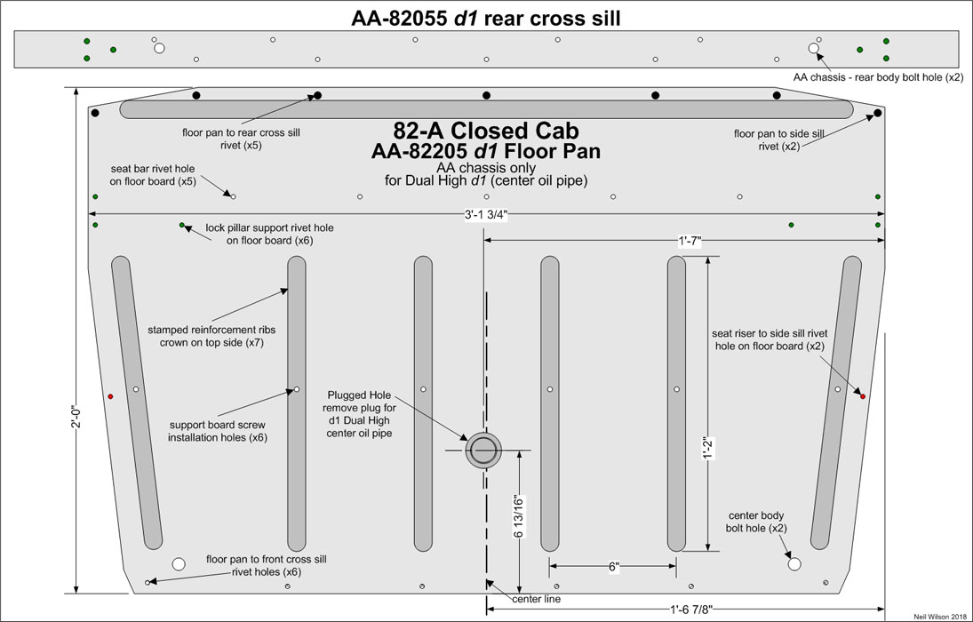
The 82-A closed cab had three AA-82205 floor pan designs:
- d1 – Used from production start through early 1928. This initial design had a hole for the d1 Dual High transmission oil pipe. The hole was located close to the center of the pan between the two stamped, center reinforcement ribs. This hole was plugged for AA’s without the factory optional Dual High transmission. The four center reinforcement ribs were all the same length.
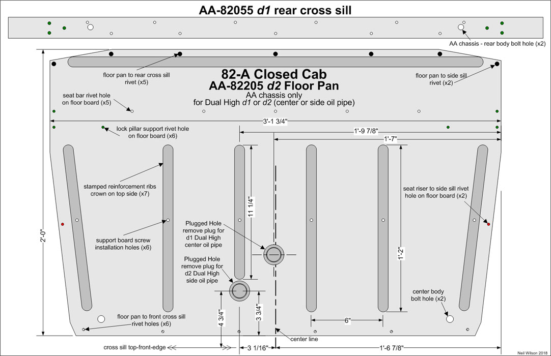
- d2 – Used March 1928 through mid 1928. This design had a second hole added for the d2 Dual High transmission oil pipe. The hole was located at the front of the shortened, 4th (from the left), reinforcement rib. Both holes were plugged for AA’s without the factory optional Dual High transmission. For AA’s with a d1 or d2 Dual High transmission, the appropriate hole was unplugged.
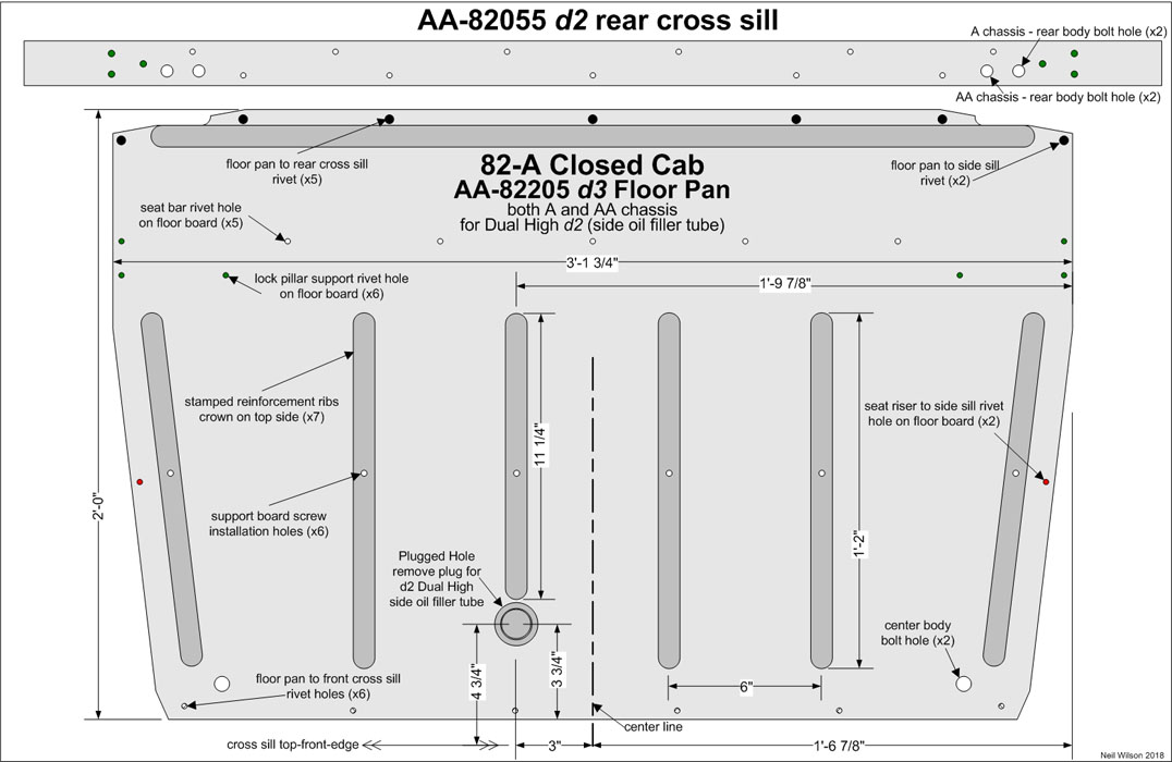
- d3 – Used April 1928 through June 1930. This design had the hole eliminated for the d1 Dual High transmission oil pipe. The rear edge of the pan was changed for clearance of an additional rear body bolt hole (one on each side). The new holes were used when the 82-A closed cab was installed on the A chassis (available starting June 4, 1928 per the RGJS).
Floor Pan Gallery
82-A Rear Window
To be researched/documented.
82-A Top & Visor
To be researched/documented.
82-A Upholstery
The 82-A closed cab had a black upholstery scheme (production start – July 1928?) and a brown upholstery scheme (August 1928? thru June 1930).
More to be researched/documented.
82-A Upholstery – Seats
To be researched/documented.
82-A Upholstery – Panels
The 82-A closed cab had cardboard upholstery panels (cowl, door, quarter, quarter panel, and windshield header)
More to be researched/documented.
82-A Upholstery – Windlace
Sub-Section Contents
Windlace Overview
The 82-A closed cab came with an Arabian grain artificial leather (black) upholstery scheme through July 1928. A Spanish brown colonial grain artificial leather (brown) upholstery scheme was used starting August 1928. Windlace assemblies were made from the color scheme’s seat upholstery material wrapped and sewn around a black, hollow, rubber core.
Windlace at the top and front of the doors were under pressure with the door closed. Note that oversized cores for these two assemblies will cause binding when closing the doors. In cold weather, the black, hollow, rubber core remained flexible for a number of years before becoming hard from age. The three outside diameters of the windlace cores are shown in the table below.
| Windlace Parts Table | |||
|---|---|---|---|
| Black | Brown | Core | Part Description |
| Neil Wilson 2021 | |||
| A-80472 | A-73472 | 3/8” | Bottom Windlace Assembly (on door) |
| A-80362 | A-73468 | 1/4″ | Top Windlace Assembly (on header above door) |
| A-80364 | A-73480 | 5/32” | Front Windlace Assembly (on door) |
| A-80366 | A-73476 | 3/8” | Rear Windlace Assembly (on lock pillar) |
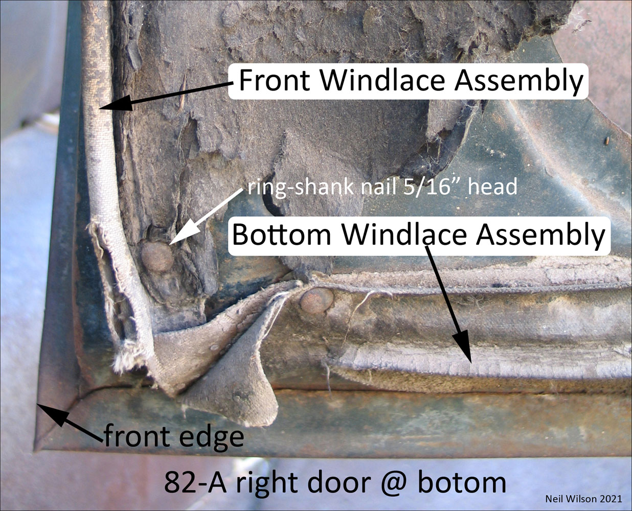
Bottom Windlace Assembly – on door
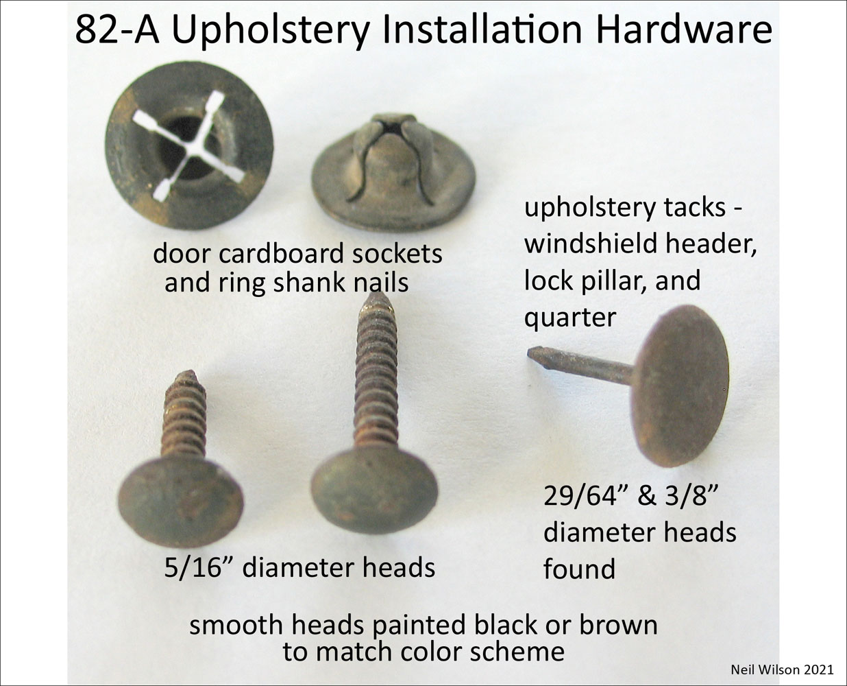
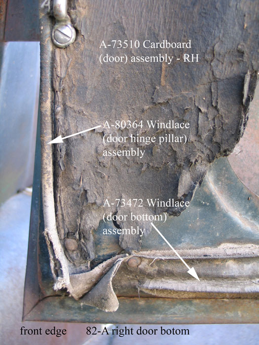
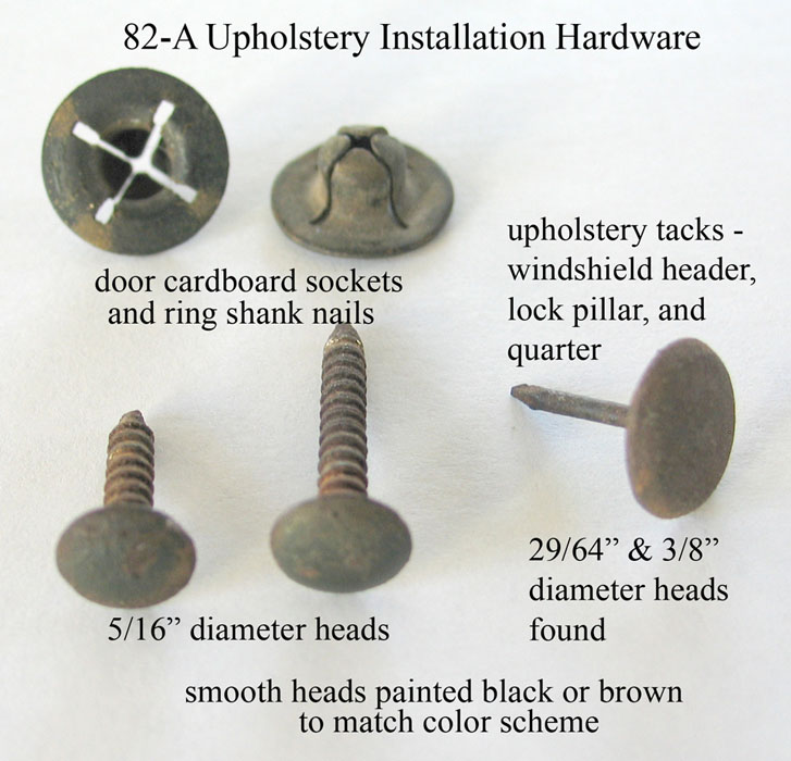
Part A-80472 (black) and A-73472 (brown) with 3/8” cores were used on the door bottoms. These windlace assemblies were hung at the door bottoms with the tails under the upholstery cardboard panel and were held in place by the ring-shank nails and sockets securing the panels to the doors. The windlace was pushed outward when the door closed.
The use of windlace at the door bottom was unique since other A-vehicles used a rubber weather strip. This windlace was used with the 82-A closed cab plus the 79-A and 85-A panel delivery bodies. All three bodies used the same door. Based on observation, the outer ends of the bottom windlace were cut blunt but the cores were likely cut short of the ends.
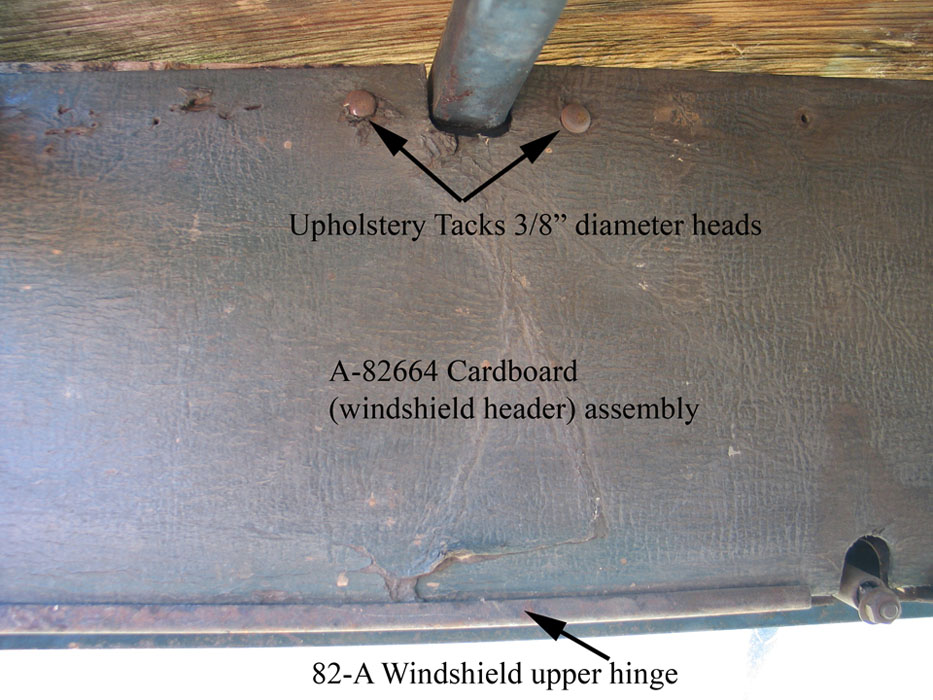
Top Windlace Assembly – on header above door
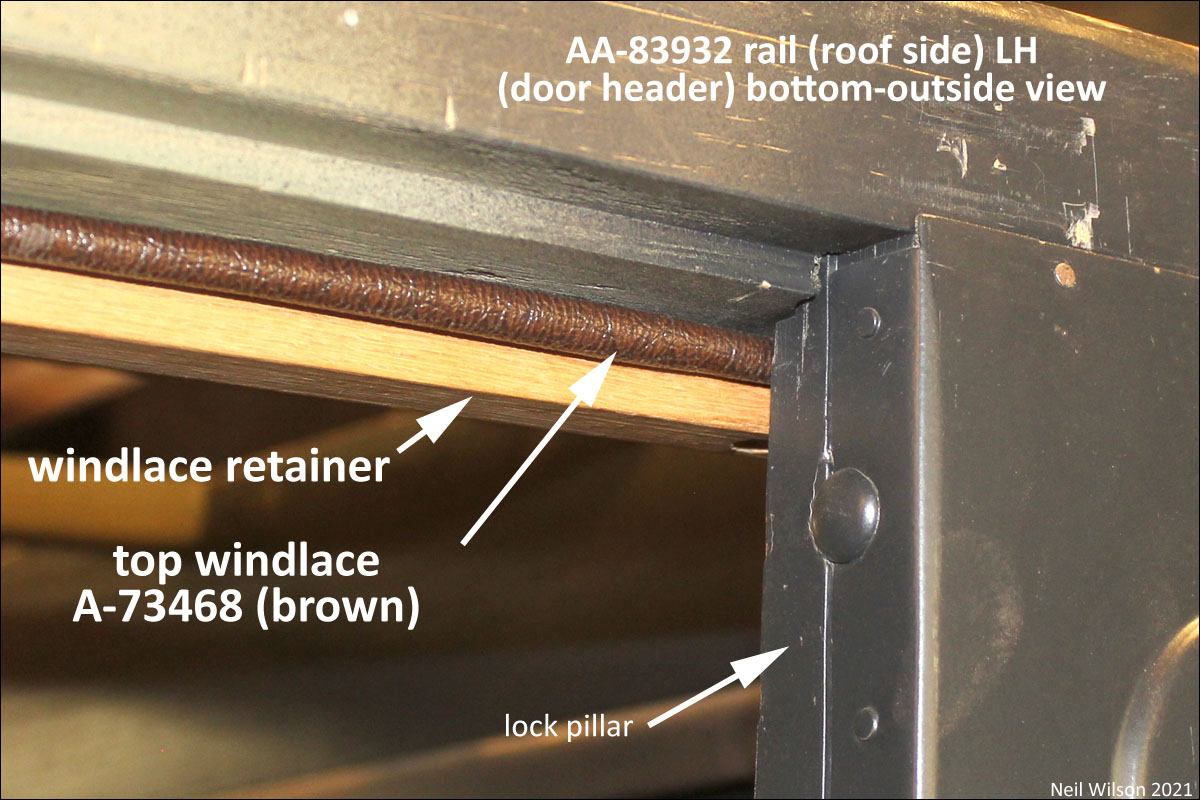
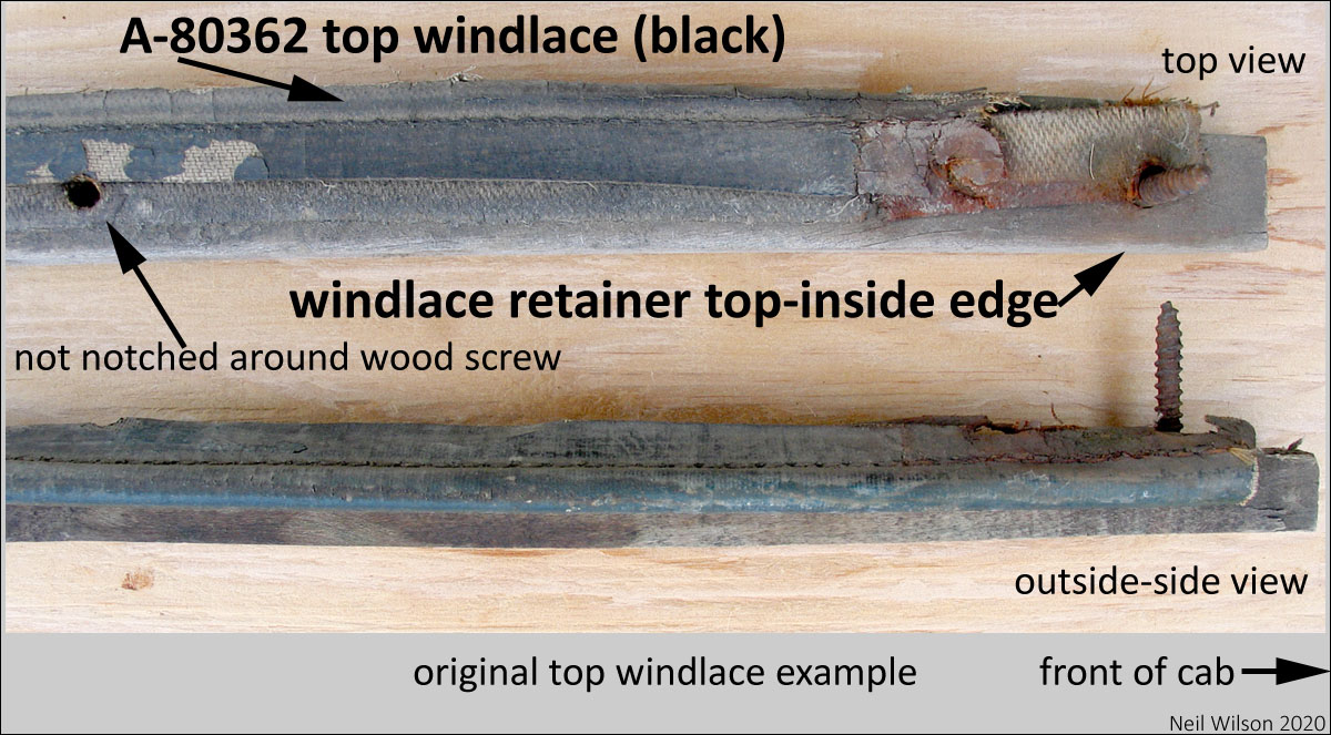
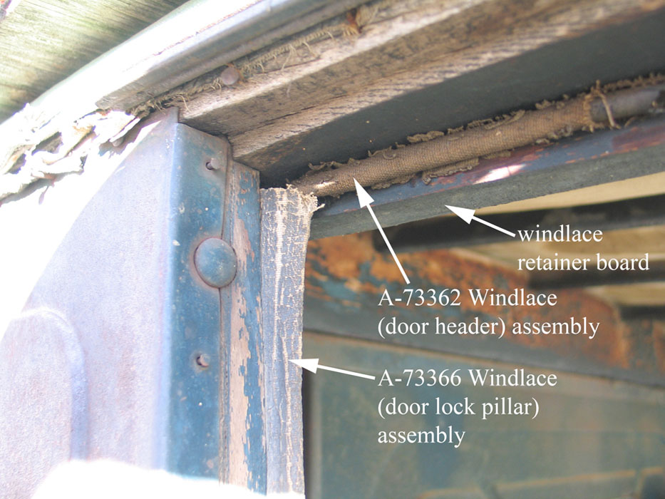
Part A-80362 (black) and A-73468 (brown) with 1/4” cores were installed between the wood headers above the doors and wood windlace retainers. This windlace was unique to the 82-A closed cab. Different top windlace assemblies were used for the 79-A and 85-A panel delivery bodies which used the same doors.
Top windlace assemblies were slightly compressed with the doors closed. Note that cores larger than 1/4” for these assemblies will interfere with easy door closing. Installation details are shown below.
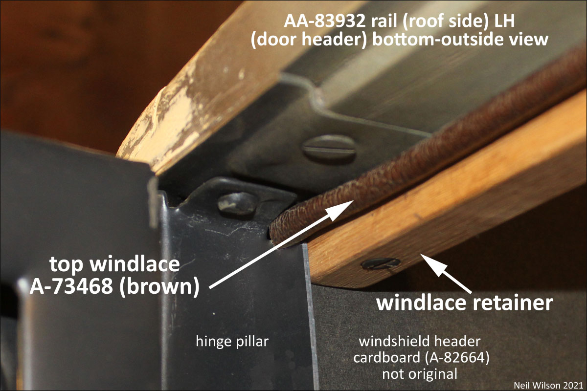
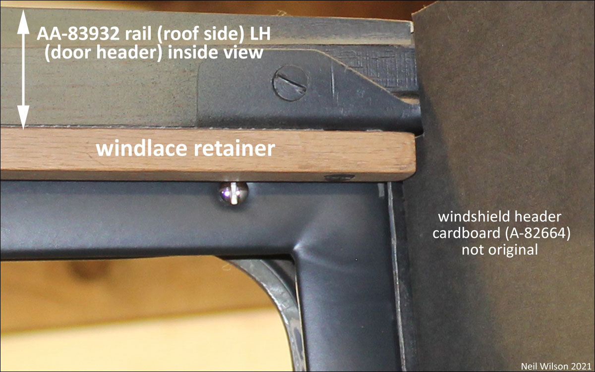
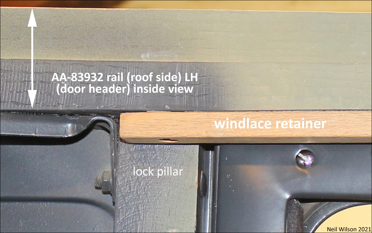
The door headers were named “side roof rails” in the Ford parts lists. The wood windlace retainers were attached to the bottom of the door headers flush with the inside-edge. Attachment was with five #10 x 1” slotted flat head wood screws. It is best to pre-drill the holes through the retainers and into the headers. The wood retainers were 29-3/4” long x 1/4” high x 3/4” wide.
The front of the retainers butted up to the windshield header cardboard upholstery panel. The rear of the retainers extended to the rear of the lock pillars (see images below).
The retainers were painted along with the cab. Evidence shows that the retainers were loosely installed with the five wood screws before painting. These retainers would have been removed after painting to allow the windshield header cardboard upholstery to be installed.
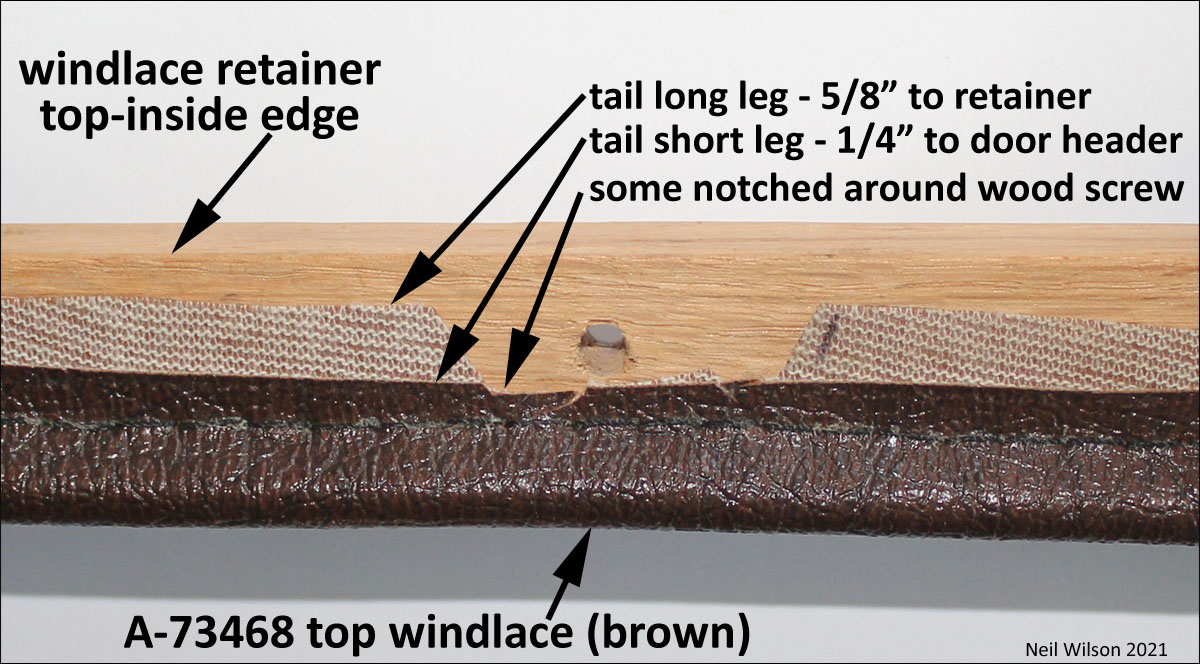
The top windlace assemblies were 29-3/4” long and had 1/4” cores. Based on observation, the ends were cut blunt. The width of the windlace tails were 1/4” and 5/8”. The 1/4” tails were installed up next to the door headers.
This step-type design resulted in the wood retainers being at a slight angel and eliminated a gap (giving a finished look). The 5/8” tails were sometimes notched to clear the retainer installation wood screws. This may have been assembly plant installation differences. Refer to the following images.
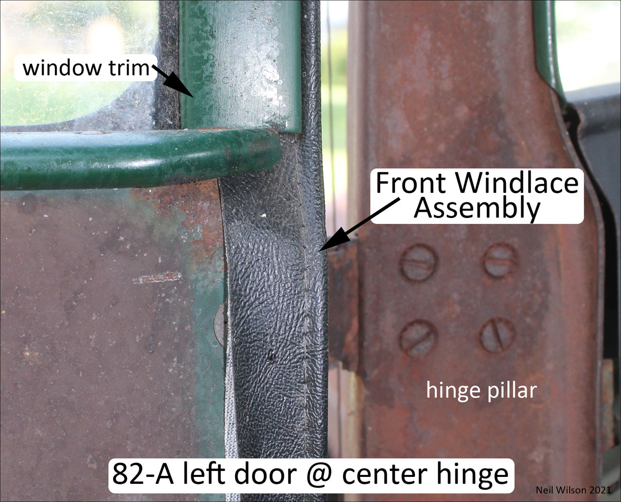
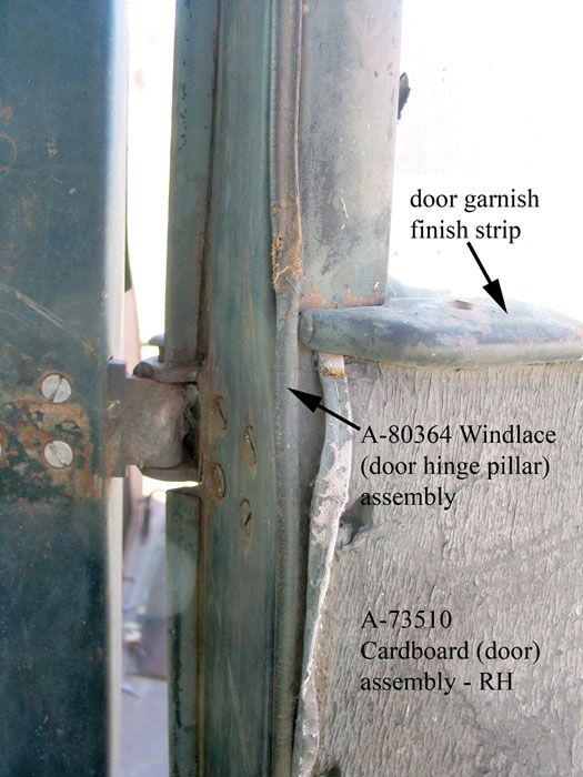
Front Windlace Assembly – on door
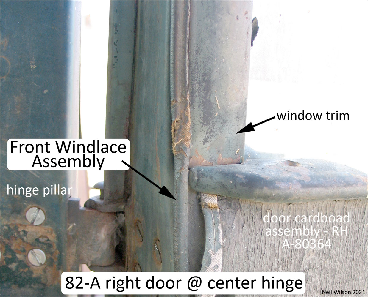
Part A-80364 – black and A-73480 – brown with 5/32” core. Front windlace was attached directly to the door. Ford’s name for this part was “windlace (door hinge pillar)”. The upper portion of the windlace was installed under the metal slide for the door finish strip (i.e. the slide for the window trim). The slide was secured with three round head screws and caged square nuts.
The lower portion of the windlace was installed under the door upholstery cardboard panel. The upholstery panel ring-shank nails and sockets securing the panels to the doors held the windlace in place. Refer to photographs following.
Note that the 5/32” core size is important. When a door is closed the windlace is compressed between the door and hinge pillar. Larger core size will bind the door by flexing the hinges.
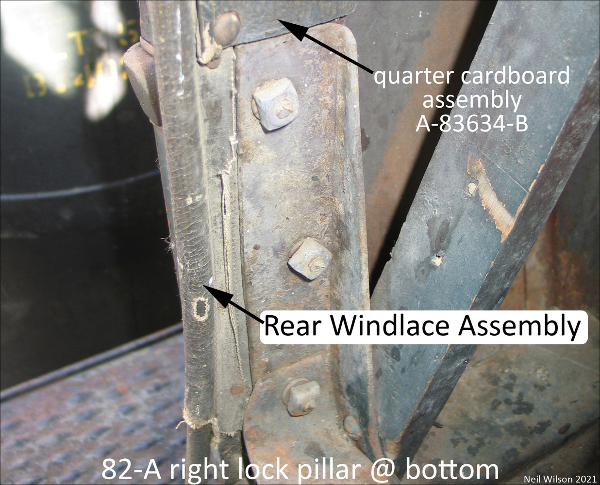
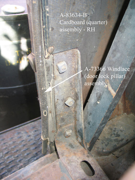
Rear Windlace Assembly – on lock pillar
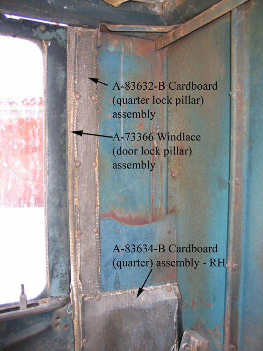
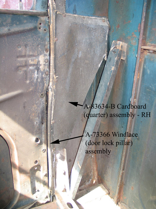
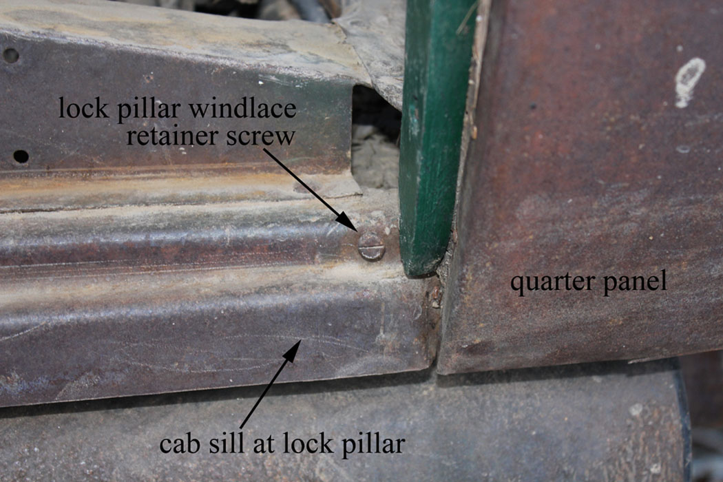
Part A-80366 – black and A-73476 – brown with 3/8” core. Rear windlace was attached to the inside faces of the lock pillars with tacks. The windlace tails were covered by the quarter lock pillar and quarter cardboard upholstery panels except for the lower section of the windlace. For this lower section, the windlace tails were hidden by the seats. The windlace was pushed inward when the door was closed.
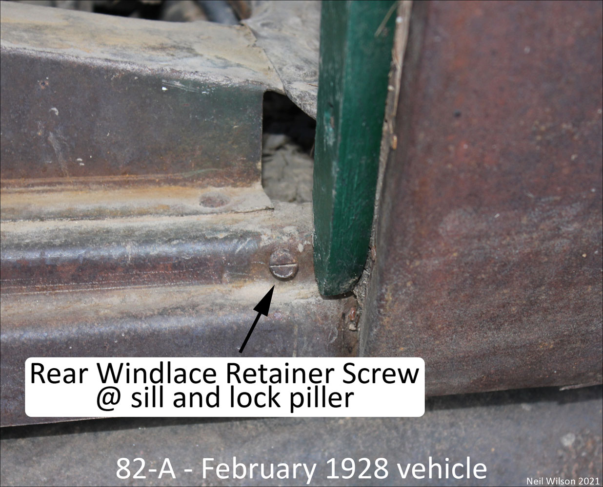
On some 82-A cabs, the rear windlace assemblies were secured to the sill with a pan head sheet metal screw. These screws have been found on both a February 1928 and a March 1930 82-A cab. Other cabs within this date range do not have the sill screw hole. It is likely that this was done at upholstery installation time as an assembly plant option. The photos below show the rear windlace and retainer screw at the cab sill.
Upholstery – Galleries
82-A Closed Cab – Seats Gallery
Add seats gallery here.
82-A Closed Cab – Upholstery Panels Gallery
Wood
To be researched/documented.
Wood – Top
To be researched/documented.
Wood – Body
To be researched/documented.
Wood – Body Blocks
To be researched/documented.
Page Contents