
2024/12/24 update
Page Contents
88-A Platform Designs
The 88-A platform body has been defined as having three designs on this site for purposes of identification.
The following is an overview of design 1, 2 and 3 followed by a gallery which illustrates each design.
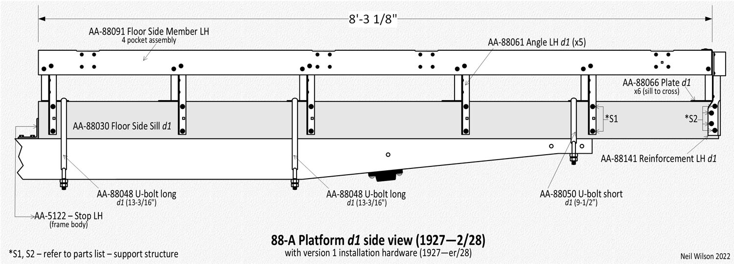
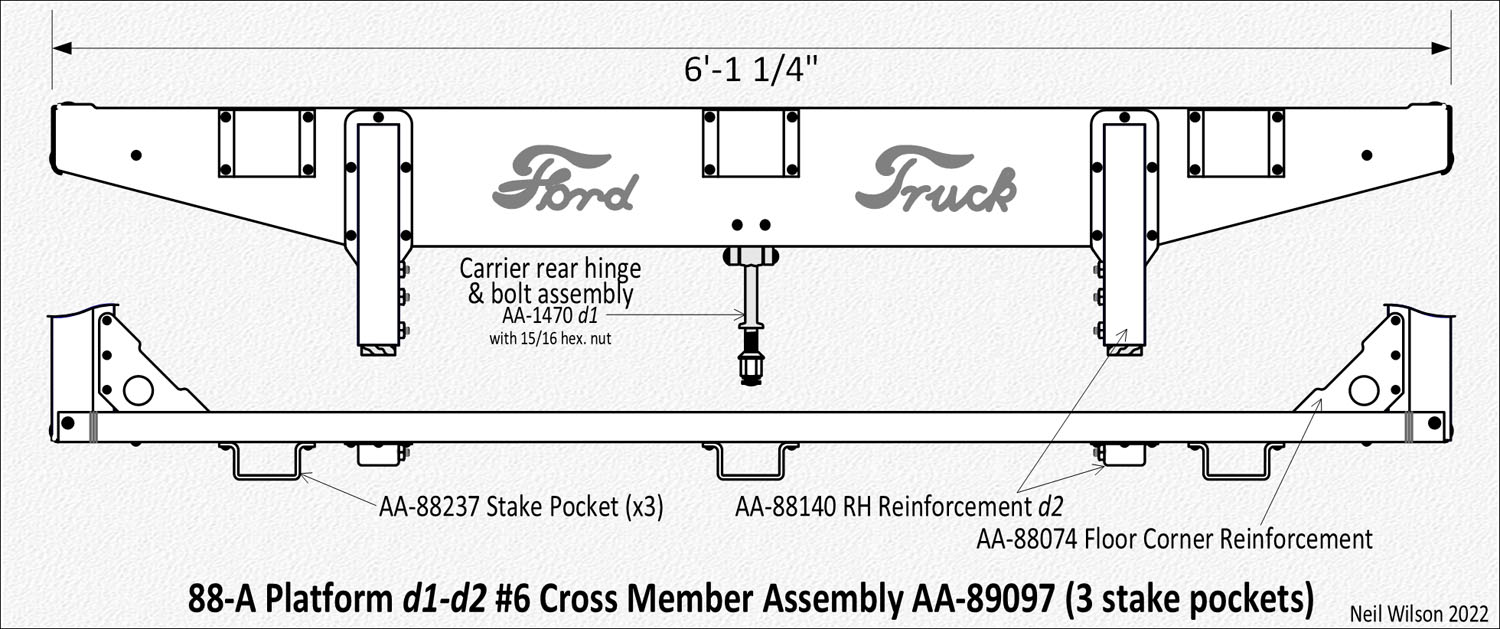
d1 (1927—2/28) – 4 side stake pockets and 3 external rear stake pockets, rear “Ford Truck” stamping, 1-1/8″ angles.
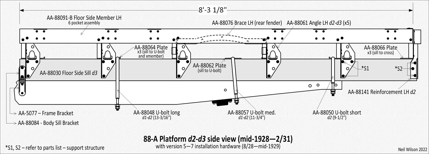
d2 (3/28—mid-28) – 6 side stake pockets and 3 external rear stake pockets, rear “Ford Truck” stamping, 3-9/16″ angles. There were d2a and d2b designs:
d2a (3/28) – Cross sill 3 and 4 did not have fender cutouts and there were no fender braces.
d2b (mid-1928) Cross sill 3 and 4 had fender cutouts and there were fender braces.
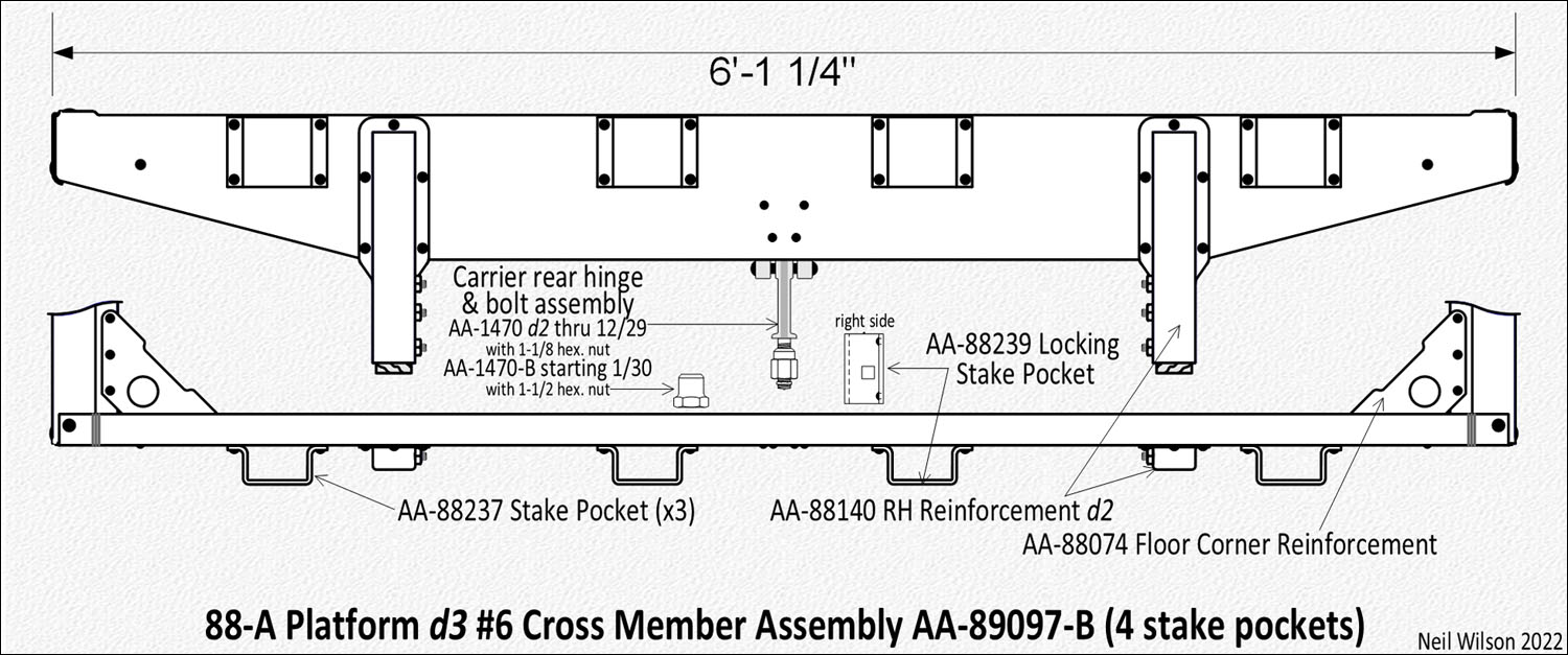
d3 (mid-28—2/31) – 6 side stake pockets and 4 external rear stake pockets, no rear stamping, 3-9/16″ angles. There were d3a and d3b designs:
d3a (mid-1928—mid-1929) – There were fender braces.
d3b (mid-1929—2/31) – There were no fender braces.
Platform Summary Gallery
88-A Platform Floor Sill Assemblies
To floor sill assembly parts listing
The 88-A platform included two floor side sill assemblies supporting the remainder of the platform body.
Each assembly consisted of a floor side sill plus plates attached to the top of the sill. Original bodies observed, have yellow pine or maple floor side sills.
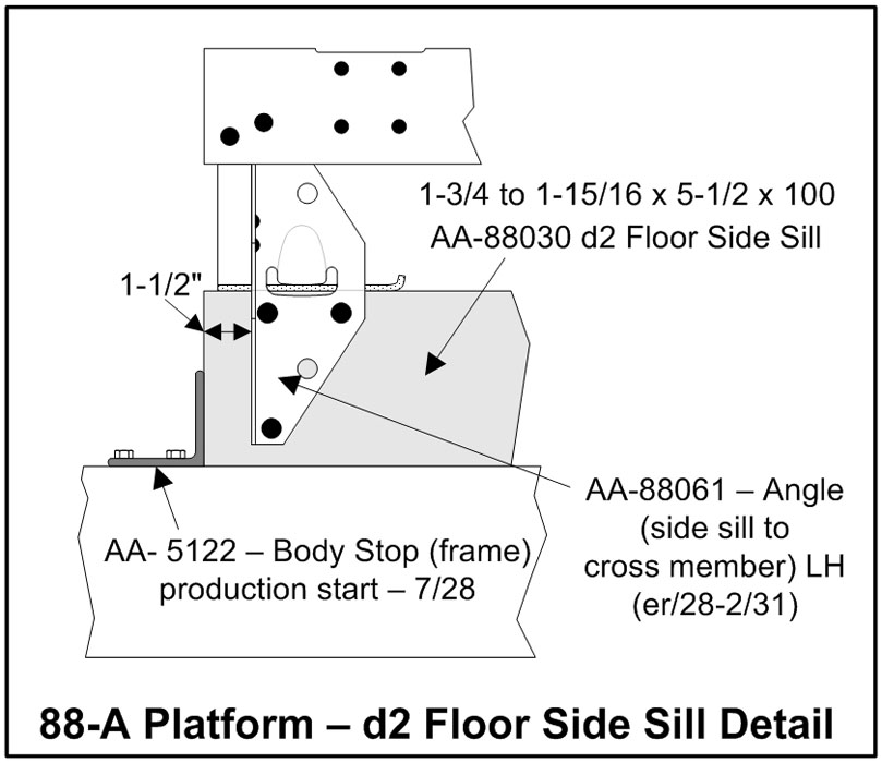
Floor Side Sill
These sills were 1-7/8″ thick (reduced to 1-3/4″ in early to mid-1928). They were 5-1/2” high by 100” long.
The initial d1 floor side sills were drilled for the attachment of 1-1/8” angles. In early-1928, 3-9/16” angles were placed into production.
This resulted in a conversion to d2 sills with new bolt hole patterns.
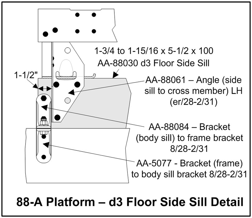
In August 1928, the body stop mounting hardware was replaced with brackets and d3 floor side sills were introduced with additional holes for bolting the brackets to the sills.
Floor Side Sill Gallery
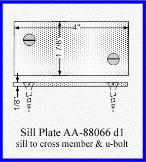
Sill Plates
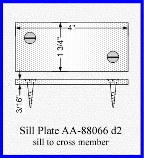
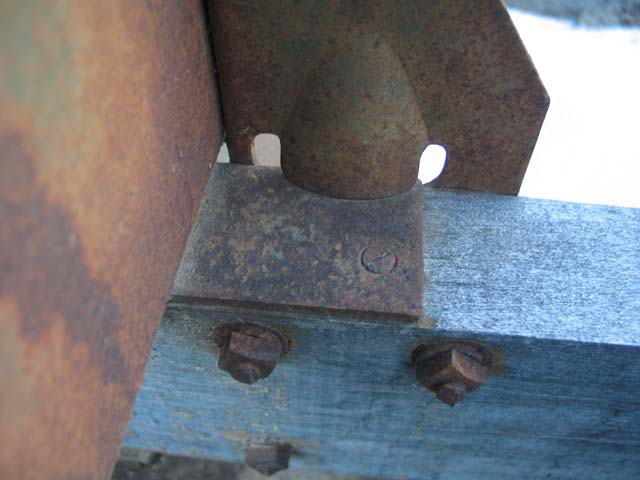
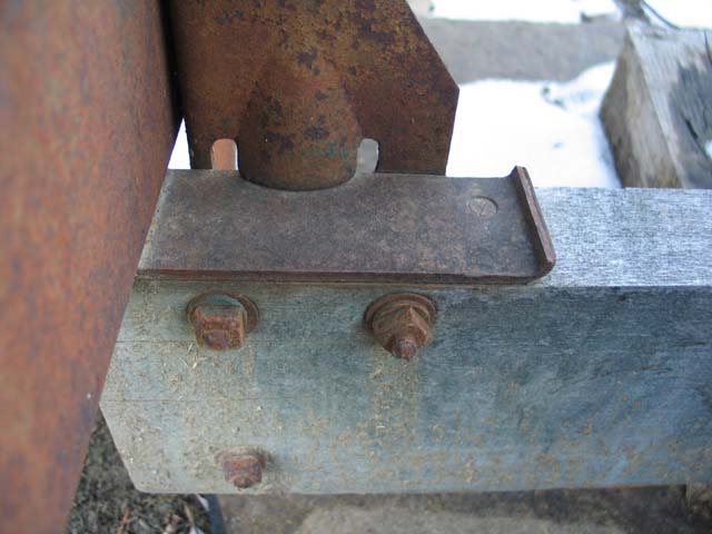
The gallery below shows the four different designs of sill plates which were installed along the tops of sills with flat head slotted wood screws. The six platform cross members were supported by these plates. Sill plate locations are shown in the platform summary gallery.
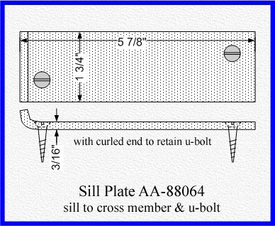
The AA-88066 d1 sill plate was 1/8″ thick and was used with 88-A platform d1. 88-A platform d2 and d3 used 3/16″ thick plates (AA-88066 d2). Sill plate AA-88064 was 5-7/8″ long with a curled end to serve as a U-bolt retainer in addition to supporting the cross member.
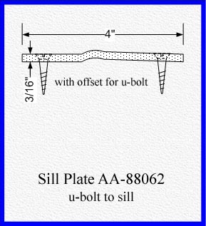
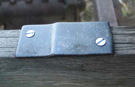
In early-1928 U-bolts were placed between cross member 3 and 4 (one on each side). This required the use of extra AA-88066 plates. In mid-1928 sill plate AA-88062 was designed for the extra, between cross members, plates. It allowed the U-bolt to be installed perpendicular to the slopped bottom side of the frame.
Each of the many installation hardware versions dictated the configuration of short and long plate usage. However, to insure backwards comparability for customers purchasing a platform from service, hardware version 5 through 8 included the long plate under floor cross member 1 even though it was not used to support a U-bolt.
Sill Plates Gallery
88-A Platform Floor Support Structure
To floor support structure parts listing
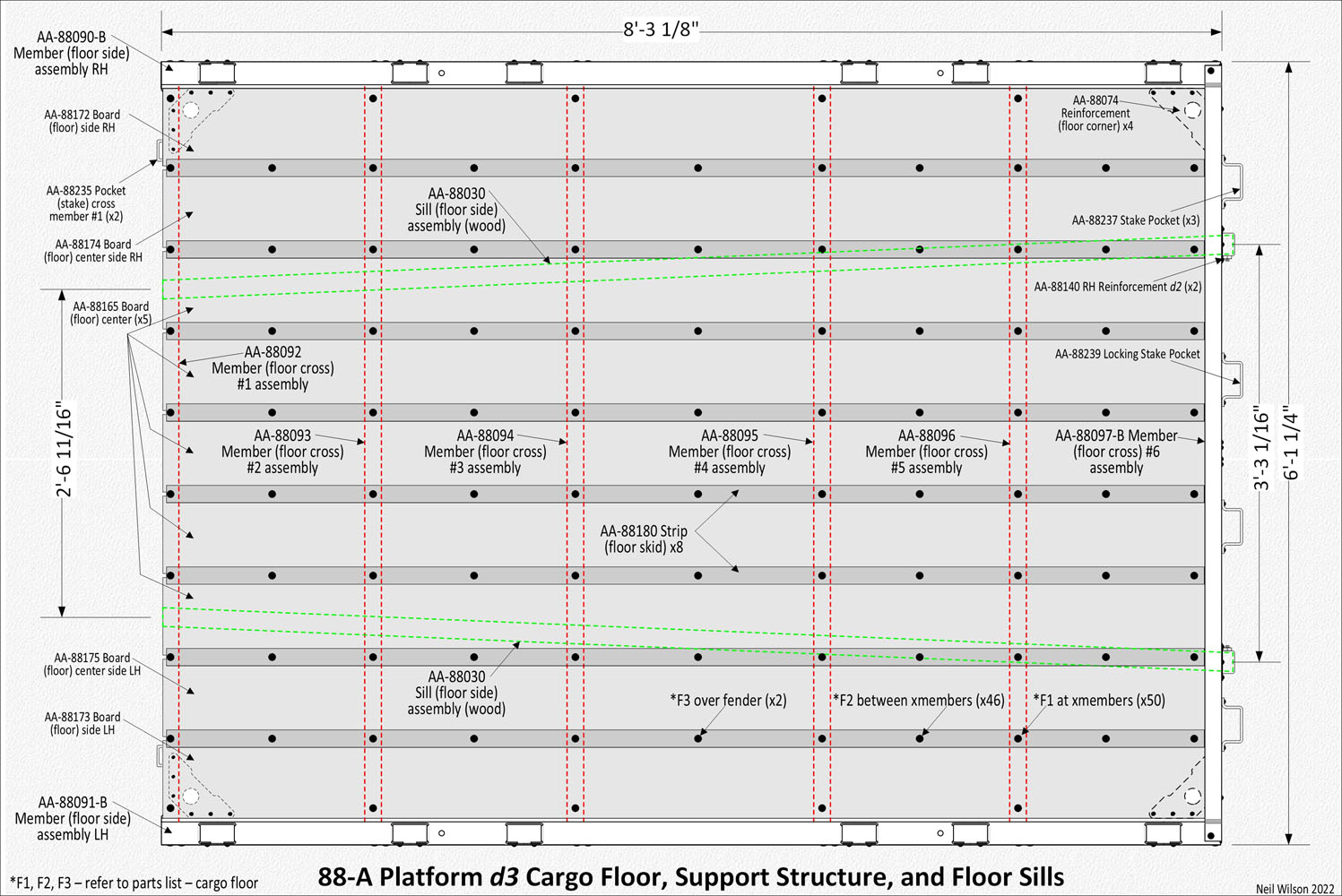
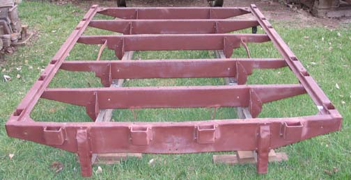
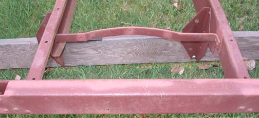
An example floor support structure for the 88-A d3 platform is shown below (also includes the wooden sills). This example shows the rear fender braces installed between cross members 3 and 4.
The support structure was made up of two floor side member assemblies (each with four or six internal stake pockets) and six floor cross member assemblies. The rear cross member had three or four pockets.
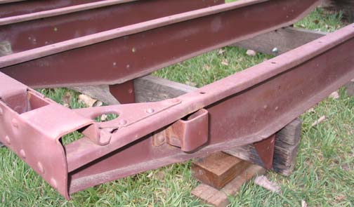
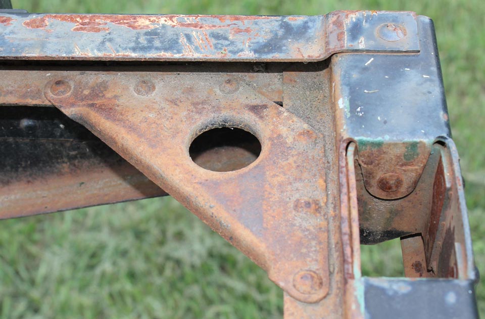
Each corner of the support structure had a triangular shaped reinforcement riveted in place (see cross members 1-5 gallery).
Each cross member 1-5 assembly was made up of a stamped steel cross member plus two angles attached with rivets. Cross member 6 assembly was made up of a stamped steel cross member, a floor board support, two reinforcements, and 3 or 4 stake pockets.
The entire stamped steel structure was assembled with rivets. Carriage bolts were used to attach the structure to the two floor side sill assemblies described above.
This support structure was the foundation for the cargo floor as well as the base for body equipment such as Ford sold 188-A stake racks, 134-A stock racks, and 134-B stock racks. Many AA platform trucks were fit with equipment supplied by other manufactures.
Floor Side Member Assemblies
The initial right/left hand assemblies were AA-88090/91 d1 and were TT platform carry-over parts with four internal stake pockets each side. These assemblies were used for 88-A platform d1. In March 1928, assemblies AA-88090/91-B d2 were introduced with six internal stake pockets on each side.
For both designs, the rear-side stake pocket had a carriage bolt hole stamped into the assembly’s face. When 188-A stake racks were installed, a carriage bolt was used to secure the side-rear rack in place. The carriage bolt hole was eliminated about April of 1928. Floor side member assemblies are shown in the platform summary gallery.
Floor Cross Member Assemblies 1-5
Each cross member had a unique design. To aid the assembly line, each cross member was stamped with a 3/8″ high number onto the front face. Numbers were stamped with enough force to be seen as a bulge on the back side of the cross member. The numbers were sometimes stamped upside down or turned to one side. This identification was eliminated in early 1929. The cross members 1-5 gallery shows the location of these numbers. Each assembly consisted of a floor cross member plus right and left hand angles riveted in place. The distance between angles on each floor cross member was progressively wider from front to back. Consequently, each assembly had a different part number.
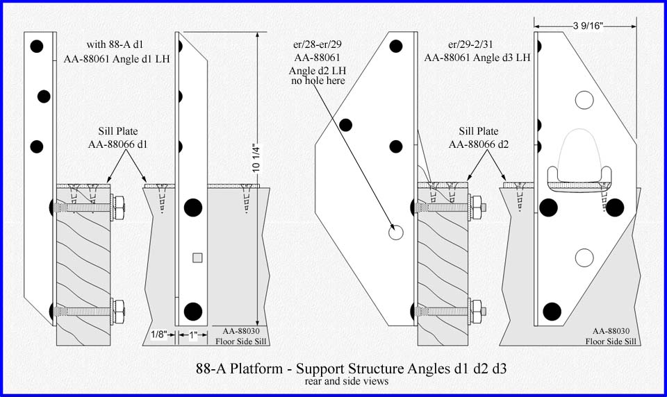
The right and left hand angles were assigned part numbers AA-88060 and AA-88061 respectively. There were three angle designs as shown in the cross members 1-5 gallery.
The d1 angles were similar to the prior TT angle. These AA angles were 1-1/8” wide by 10-1/4” long. The d2 angles were 3-9/16” wide by 10-1/4” long with an offset stamped into the sill-side face which allowed the angle to rest on top of a sill plate. The d3 angles were identical to d2 angles except for an extra 1/2” hole punched in the cross-member-side face of the angle.
Floor cross member assemblies 1 and 2 did not change during 88-A platform production except for different angle designs.
Floor cross member 1 included two external stake pockets which were TT carryover parts. They were designed for 1/4” thick by 1-17/32” wide strap iron stakes and can be see in the cross members 1-5 gallery.
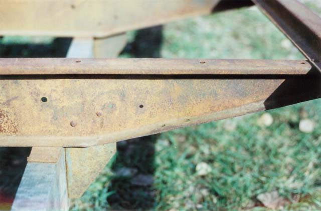
Rear fenders for platform bodies were a production option from er/28—7/11/29. In er/28, floor cross members 3 and 4 were modified to included some 1/4” holes. These holes are believed to be for the attachment of rear fender brackets AA-16432, AA-16433, AA-16434, and AA-16435.
These brackets were used with rear fenders AA-16428 RH and AA-16429 LH. Samples of these brackets and fenders have not be found. Both d1 and d2 angles were used with these floor cross member. In early-1928, floor cross members 3 and 4 d3 were released as shown in the cross members 1-5 gallery. These assemblies included cut outs for new rear fenders AA-16438 RH and AA-16439 LH. In addition, a rear fender brace was attached with rivets between floor cross members 3 and 4 on each side of the body as shown in the platform summary gallery and in the cross members 1-5 gallery.
Cross Members 1-5 Gallery
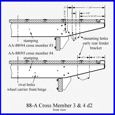
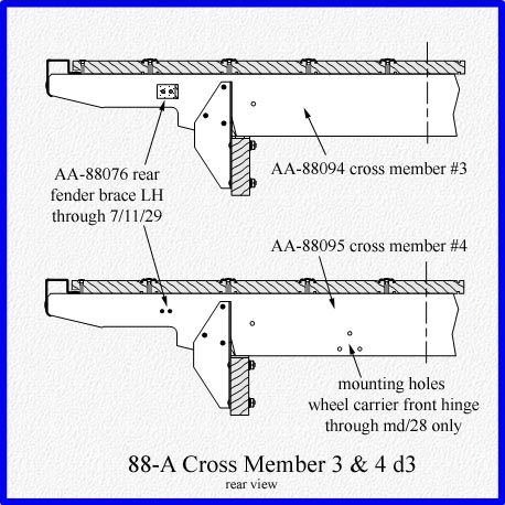
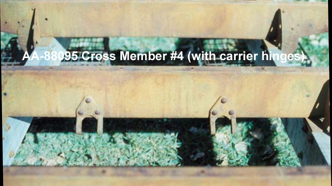
Floor cross member 4 had the front hinges of the initial AA-1453 wheel carrier riveted to it as shown in the cross members 1-5 gallery. In July 1928 the rivet holes were eliminated since a new AA-1453-B wheel carrier was put into production. It was attached to the frame’s new, additional, fifth cross member.
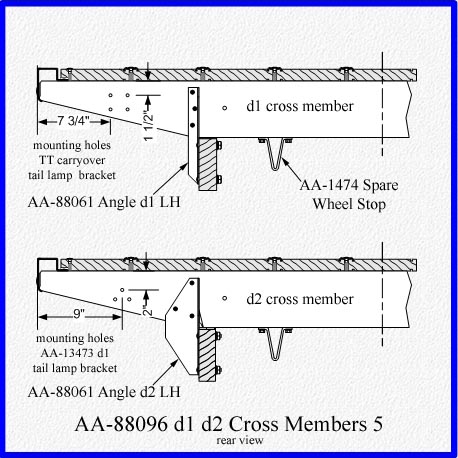
Cross members 1-5 gallery shows floor cross member 5 with tail lamp support mounting holes. The holes were punched on the left side and sometimes on the right side as well.
Initially there were four holes for a stamped steel tail lamp support which was a TT carry-over part. Starting in early-1928, there were three holes for a forged steel tail lamp support. By August 1928 the holes were eliminated and the tail lamp was moved to the frame.
This cross member also had the “V” shaped wheel stops installed along the lower flange. These stops pushed against the spare wheel to prevent rattles.
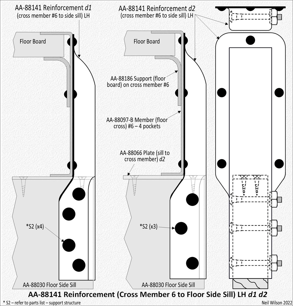
Floor Cross Member Assembly 6
This assembly included a right angle floor board support which ran the width of the cross member and faced the inside of the body. Two reinforcements which capped the rear end of the side sills were riveted to this assembly. The earliest reinforcement used four bolts for side sill connection. In early 28, this was changed to three bolt holes. The cross member 6 gallery shows these parts.
The initial AA-88097 rear cross member assembly included three external stake pockets with the words “Ford Truck” in raised script.
Some of the later three pocket cross members had a center pocket with a hole for a locking stake as was used with the four pocket cross member.
In mid-1928, AA-88097-B cross member 6 was placed into production and the “Ford Truck” script stamping was eliminated. It had four external stake pockets in which the center-right stake pocket had a 5/8” square hole in the pocket’s right side. This hole accommodated a latch built into a locking stake. The 88-A cross member 6 gallery shows this cross member.
Cross Member 6 Gallery

88-A Platform Cargo Floor – to parts listing
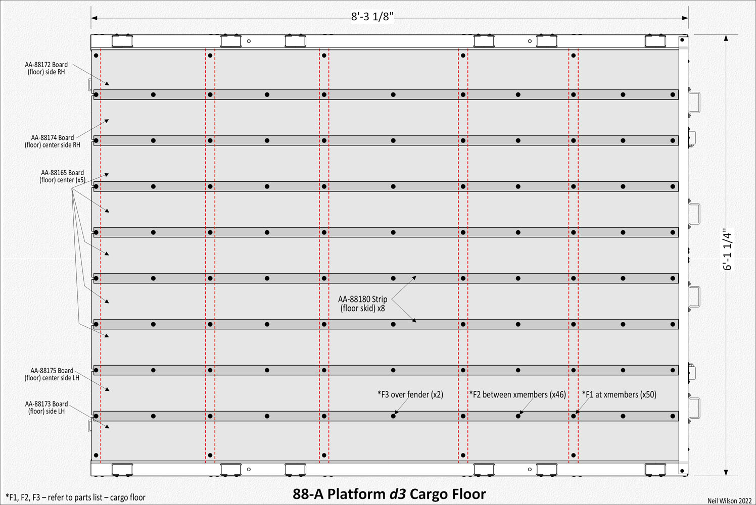
The cargo floor was made up of nine floor boards and eight skid strips.
The cargo floor gallery contains a top view detailed drawing of the 88-A platform.
Floor Boards
There were nine floor boards running the length of the body. Each board was 1-1/4” thick, 7-1/4” wide, and 98-1/2” long. However, the two outside boards may have been slightly wider since there should be about 1/4″ space between the side members and the floor boards. Original bodies observed had yellow pine boards. Some early-1928 bodies observed had maple floor boards.
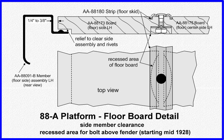
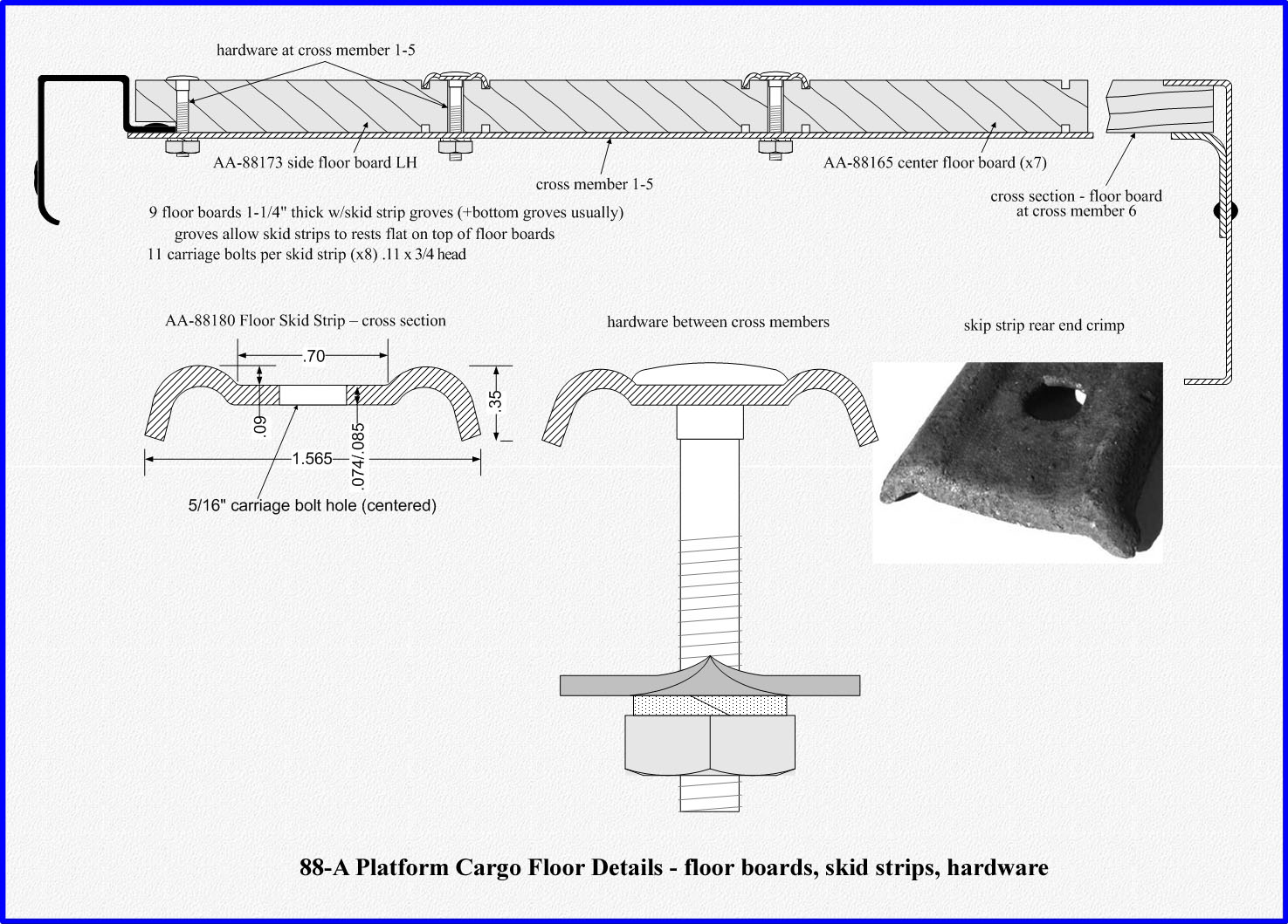
The floor boards were grooved to allow the legs of the skid strips to be countersunk (allowing the trough of a skid strip to rest on the top of the floor boards). Initially the groves were on the top side only. The groves were on both sides of the floor boards starting in mid to late 1928 or possibly early 1929. However, the bottom groves served no purpose.
The outside edges of the right and left hand side floor boards were attached with carriage bolts which ran through the boards at floor cross members 1-5.
To allow the boards to lay flat, their undersides had recesses to provide clearance for the side members and corner reinforcements.
Initially the skid strip bolts above rear fenders extended through a hole in the fenders. In mid-1928 shorter carriage bolts were installed in the skid strips above each rear fender and the fender hole was eliminated. The bottoms of the floor boards over the fenders had a half moon shaped recess to allow for the installation of the shorter length carriage bolts. The cargo floor gallery shows this floor board recess.
The rear top edge of all floor boards had a 1/8” by 1-3/16” relief to allow the boards to slide under and be flush with the top flange of cross member 6 as can be seen in the cargo floor gallery.
Skid Strips
Eight, 97-1/8″ long, metal skid strips straddled each pair of boards and each was installed with eleven 5/16″ carriage bolt which ran between boards. The strips were bolted to floor cross members 1-5. Halfway between each floor cross member, and at the rear of the skid strips, were additional carriage bolts.
These bolts used square washers to span the gap between boards. The rear end of each skid strip was crimped to allow cargo to be loaded smoothly. Details of skid strip installation is found in the cargo floor gallery.
Cargo Floor Gallery
88-A Platform Installation Hardware
Installation Hardware Gallery
Installation Hardware Versions
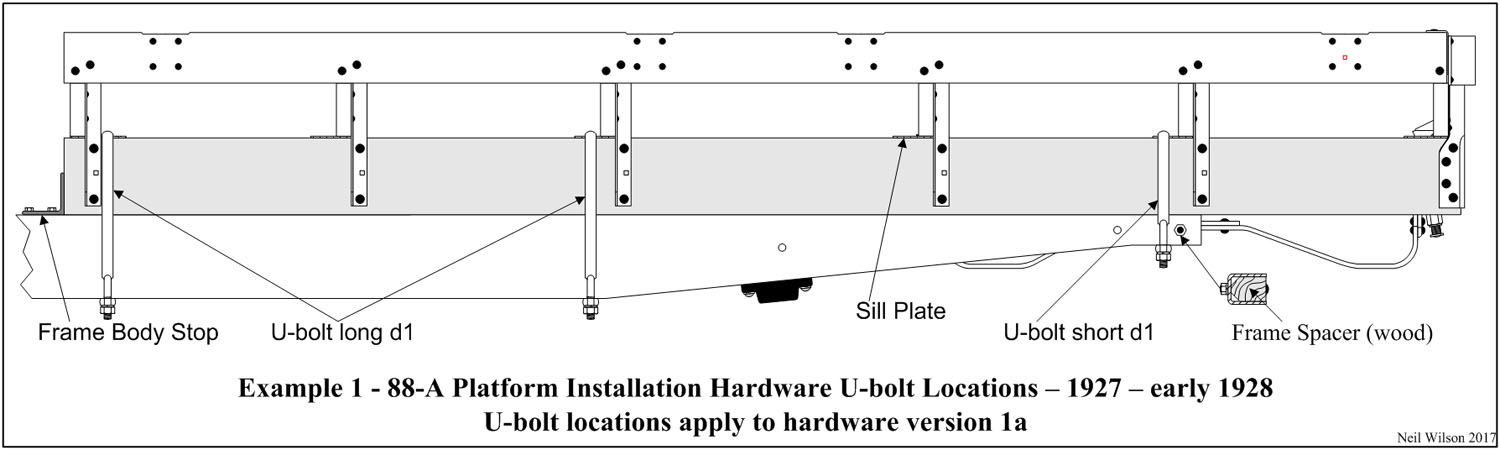
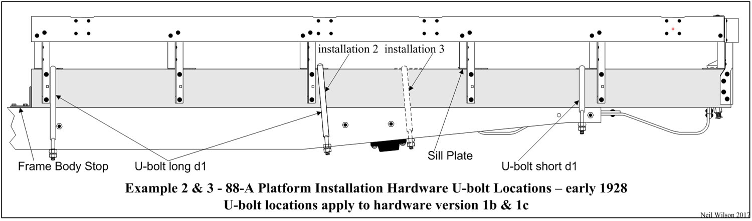
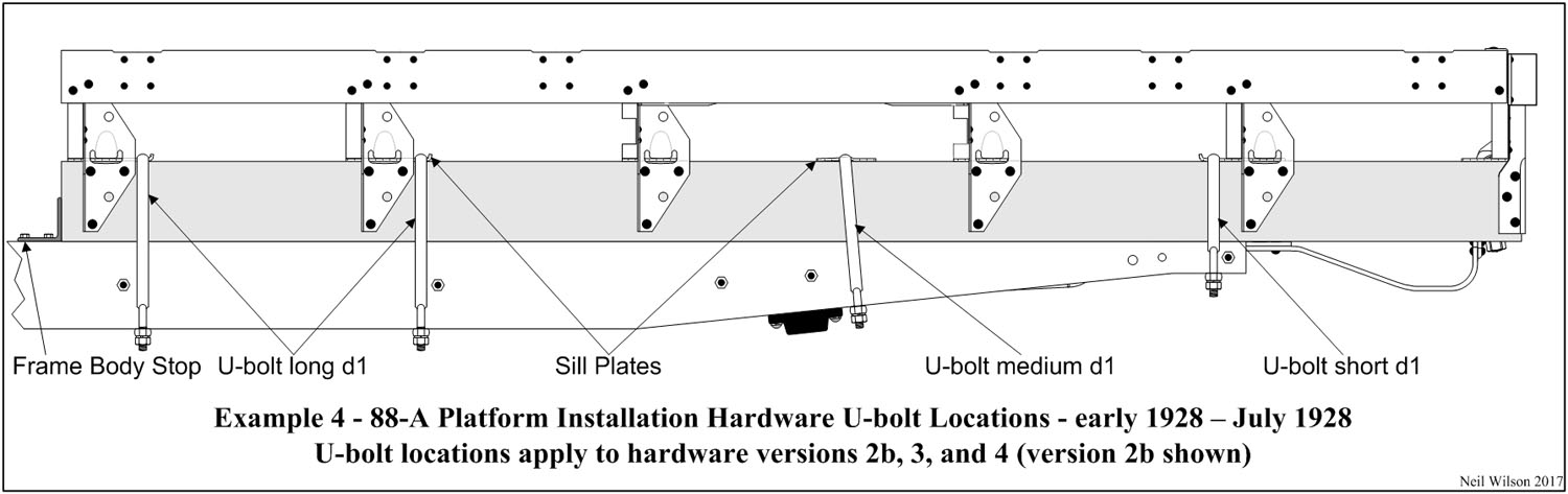
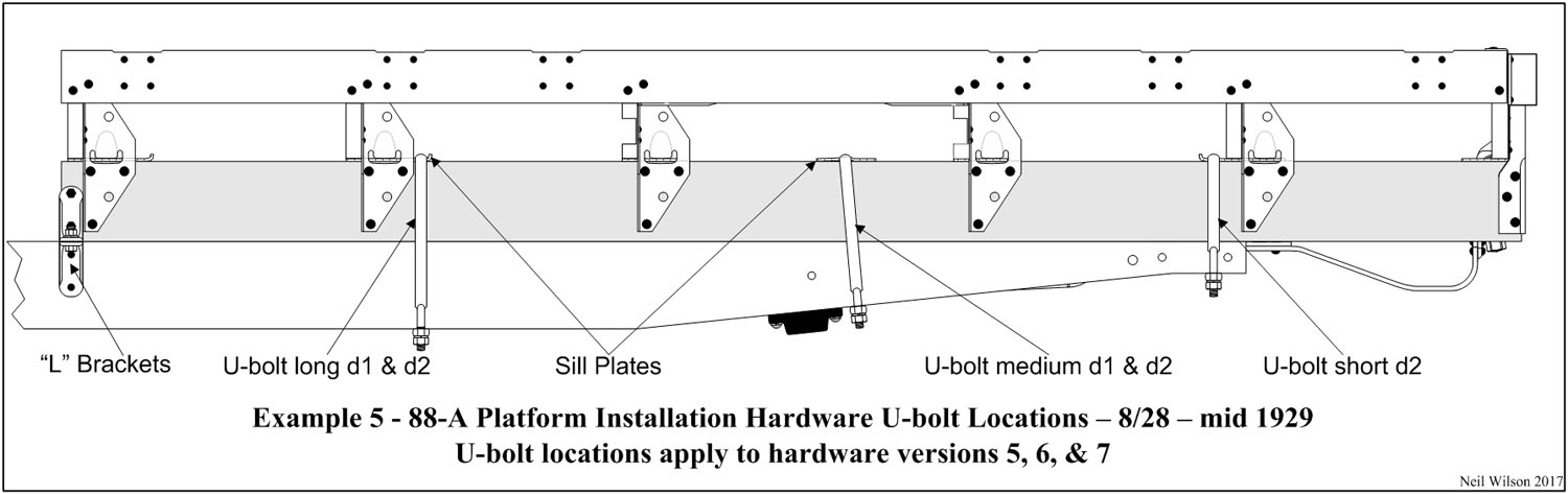
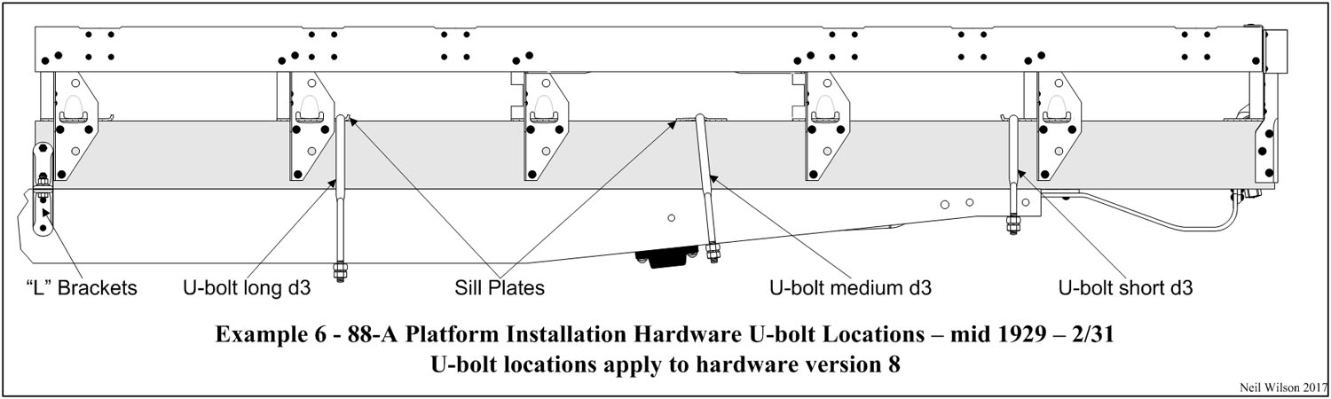
The 88-A installation hardware included U-bolt/bar assemblies. During the production period (12/27—2/31), there were three U-bolt designs and several different locations for these assemblies. U-bolts were hung over the sill plates attached to the top of the platform sill. Each U-bolt had a bar under the frame which spanned and was bolted to the U-bolt legs. Starting 8/28, the forward U-bolts were replaced with body-sill-to-frame brackets (i.e. “L” brackets) bolted to the outside face of the wood sills. The gallery below shows this hardware.
For a given 88-A Platform installation, U-bolts and “L” brackets plus frame parts were used in combinations of eight versions as shown in the Hardware-Versions-Table following.
The platform body and frame used on the assembly line would have varied at the assembly plants due to shipping and usage. Consequently, the hardware version usage dates shown in the table are approximate production dates only.
The various frame parts used for either an 88-A Platform or 89-A Express installation are found on the Frame Brackets page. The following are direct links to the various parts associated with 88-A platform installations:
| 88-A Platform Installation Hardware Versions Table | |||
|---|---|---|---|
| Neil Wilson 2022 | |||
| VERSION 1a, b, c – 12/27—er/28 with Frame AA-5005 d1 | |||
| ….Frame with – all wood spacer bolt holes punched | |||
| Back of cab | 1 | AA-5121 | Stop (frame body) RH |
| 1 | AA-5122 | Stop (frame body) LH | |
| Front | 2 | AA-88048 d1 | U-Bolt long |
| Center | 2 | AA-88048 d1 | U-Bolt long |
| Rear | 2 | AA-88050 d1 | U-Bolt short (w/long bar) |
| 2 | AA- 5115 | Frame Spacer (wood) | |
| Version 1a – center U-bolts at cross member 3 front side | |||
| Version 1b – center U-bolts at cross member 3 back side | |||
| Version 1c – center U-bolts between cross member 3 & 4 | |||
| VERSION 2a, b – er/28—4/28 with Frame AA-5005 d1 | |||
| ….Frame with – all wood spacer bolt holes punched | |||
| Back of cab | 1 | AA- 5121 | Stop (frame body) RH |
| 1 | AA- 5122 | Stop (frame body) LH | |
| Front | 2 | AA-88048 d1 | U-Bolt long |
| 2 | AA- 5116 | Frame Spacer (wood) | |
| Center-Forward | 2 | AA-88048 d1 | U-Bolt long |
| 2 | AA- 5116 | Frame Spacer (wood) | |
| Center-Back | 2 | AA-88057 d1 | U-Bolt medium |
| 1 | AA- ???? | Frame Spacer (wood) RH | |
| 1 | AA- ???? | Frame Spacer (wood) LH | |
| At Axle | 2 | AA- 5117 | Frame Spacer (wood) |
| Rear | 2 | AA-88050 d1 | U-Bolt short (w/long bar) |
| 2 | AA- 5115 | Frame Spacer (wood) | |
| Note 2a/b – U-bolts = d1; center-forward U-bolts at cross member 2 back side | |||
| Note 2a – center-back U-bolts at cross member 3 back side with sill plate curled to back | |||
| Note 2b – center-back U-bolts at axle bumper with AA-88062 sill plate | |||
| 2a to 2b conversion – center-back frame spacers may have no longer been necessary since the frame spacers above the rear axle bumpers would have served the needed function. This may explain why these two parts are not listed in the April 15, 1928 AA Parts Price List. Observations in the field indicate these center-back frame spacers continued to be used as late as July 1928. | |||
| VERSION 3 – 5/28—6/28 with Frame AA-5005 d1 | |||
| ….Frame with both wood spacer bolt holes and rivet-on spacer rivet holes punched | |||
| Back of cab | 1 | AA- 5121 | Stop (frame body) RH |
| 1 | AA- 5122 | Stop (frame body) LH | |
| Front | 2 | AA-88048 d1 | U-Bolt long |
| 2 | AA- 5116-B | Frame Spacer (rivet-on) | |
| Center-Forward | 2 | AA-88048 d1 | U-Bolt long |
| 2 | AA- 5116-B | Frame Spacer (rivet-on) | |
| Center-Back | 2 | AA-88057 d1 | U-Bolt medium |
| 1 | AA- ???? | Frame Spacer (wood) RH | |
| 1 | AA- ???? | Frame Spacer (wood) LH | |
| At Axle | 2 | AA- 5117 | Frame Spacer (wood) |
| Rear | 2 | AA-88050 d1 | U-Bolt short (w/long bar) |
| 2 | AA- 5115 | Frame Spacer (wood) | |
| Note – same U-bolt locations as version 2b | |||
| VERSION 4 – 7/28 with Frame AA-5005 d2 | |||
| ….Frame with all rivet-on spacer rivet holes punched | |||
| Back of cab | 1 | AA- 5121 | Stop (frame body) RH |
| 1 | AA- 5122 | Stop (frame body) LH | |
| Front | 2 | AA-88048 d1 | U-Bolt long |
| 2 | AA- 5116-B | Frame Spacer (rivet-on) | |
| Center-Forward | 2 | AA-88048 d1 | U-Bolt long |
| 2 | AA- 5116-B | Frame Spacer (rivet-on) | |
| At Axle | 2 | AA-88057 d1 | U-Bolt medium |
| 2 | AA- 5117-B | Frame Spacer (rivet-on) | |
| Rear | 2 | AA-88050 d2 | U-Bolt short (w/short bar) |
| 2 | AA- 5115-B | Frame Spacer (sleeve) | |
| Note – medium U-bolt located at axle bumper back side; with clipped frame (starting in April 1928) AA-88050 d2 short U-bolt used AA-88054 short bar | |||
| VERSION 5 – 8/28—er/29 with Frame AA-5005 d2 | |||
| ….Frame with all rivet-on spacer rivet holes punched | |||
| Front | 2 | AA-88048 | Bracket (sill to frame) |
| 2 | AA- 5077 | Bracket (frame to sill) | |
| Center-Forward | 2 | AA-88048 d1 | U-Bolt long |
| 2 | AA-5116-B | Frame Spacer (rivet-on) | |
| At Axle | 2 | AA-88057 d1 | U-Bolt medium |
| 2 | AA- 5117-B | Frame Spacer (rivet-on) | |
| Rear | 2 | AA-88050 d2 | U-Bolt short (w/short bar) |
| 2 | AA- 5115-B | Frame Spacer (sleeve) | |
| Note – front brackets rather than U-bolts; remaining U-bolt locations = version 4 | |||
| VERSION 6 – lt/28—er/29 with Frame AA-5005 d2 | |||
| ….Frame with no rivet-on spacer rivet holes punched | |||
| Front | 2 | AA-88084 | Bracket (sill to frame) |
| 2 | AA-5077 | Bracket (frame to sill) | |
| Center-Forward | 2 | AA-88048 d2 | U-Bolt long |
| 2 | AA- 5116-C | Frame Spacer (sleeve) | |
| At Axle | 2 | AA-88057 d2 | U-Bolt medium |
| 1 | AA- 5117-C | Frame Spacer (sleeve) RH | |
| 1 | AA- 5118 | Frame Spacer (sleeve) LH | |
| Rear | 2 | AA-88050 d2 | U-Bolt short (w/short bar) |
| 2 | AA- 5115-B | Frame Spacer (sleeve) | |
| Note – front brackets rather than U-bolts; remaining U-bolt locations = version 4 | |||
| VERSION 7 – lt/28—md/29 with Frame AA-5005 d2 | |||
| ….Frame with no rivet-on spacer rivet holes punched | |||
| Front | 2 | AA-88084 | Bracket (sill to frame) |
| 2 | AA- 5077 | Bracket (frame to sill) | |
| Center-Forward | 2 | AA-88048 d2 | U-Bolt long |
| 2 | AA- 5116-C | Frame Spacer (sleeve) | |
| At Axle | 2 | AA-88057 d2 | U-Bolt medium |
| 2 | AA- 5117-C | Frame Spacer (sleeve) | |
| Rear | 2 | AA-88050 d2 | U-Bolt short (w/short bar) |
| 2 | AA- 5115-B | Frame Spacer (sleeve) | |
| Note – front brackets rather than U-bolts; remaining U-bolt locations = version 4 | |||
| VERSION 8 – md/29—2/31 with Frame AA-5005 d2 or AA-5005-B d1 | |||
| ….Frame with no rivet-on spacer rivet holes punched | |||
| Front | 2 | AA-88084 | Bracket (sill to frame) |
| 2 | AA- 5077 | Bracket (frame to sill) | |
| Center-Forward | 2 | AA-88048 d3 | U-Bolt long |
| 2 | AA- 5116-C | Frame Spacer (sleeve) | |
| At Axle | 2 | AA-88057 d3 | U-Bolt medium |
| 2 | AA- 5117-C | Frame Spacer (sleeve) | |
| Rear | 2 | AA-88050 d3 | U-Bolt short |
| 2 | AA- 5115-B | Frame Spacer (sleeve) | |
| Note – front brackets rather than U-bolts; remaining U-bolt locations = version 4 | |||
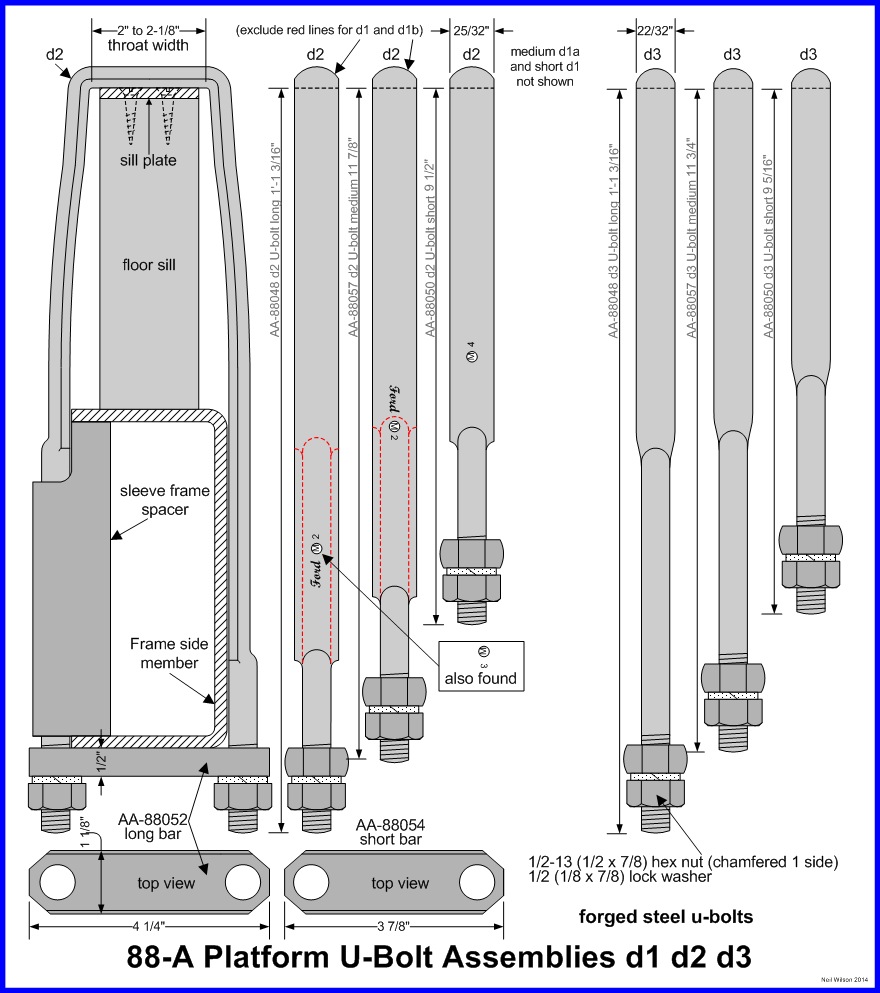
U-Bolts
The U-bolts which are listed for the various installation hardware versions above were forged steel. Across the top and down each leg, the U-bolt had a semi circular (half round) cross section. The lower section of the legs were 1/2” round-bolts with 1/2-13 threads on the last 1-1/2” to 1-3/4”.
U-bolt designs evolved without changes to their part numbers. Progressive changes were made to the width and length of the semi circular sections on the U-bolt legs. The progression was primarily due to the conversion of frame spacers to the sleeve design. Initial d1 U-bolts could not be inserted through the sleeve spacers since the round-bolt section of the legs was too short.
The gallery provides U-bolt details. The installation of the unique d2, long U-bolt is shown in the gallery. The leg with the longer round-bolt section is on the inside of the frame allowing the sleeve frame spacer to be used.
Also shown is the outside face view of the two d2 U-bolts with dashed red lines showing the inside legs. The long d1 and the medium d1 U-bolts had both inside and outside legs identical. D1 short U-bolts used the long cross bar. D2 short U-bolt used the short cross bar. The three d3 U-bolts are also shown in the gallery. These U-bolts contained no manufacturing identifications or Ford script. U-bolt designs are described in the identification table below.
The long AA-88052 cross bar was used for all U-bolts with full width frames through about June 1928. As early as April 1928 the side members were clipped at the rear. Consequently, the short AA-88054 cross bar was used for the rear U-bolts. There were two hex nuts and lock washers used to tighten the cross bar and secure the platform to the frame.
88-A Platform U-Bolt Identification Table
| U-Bolt | Part-Design | Length | Semi Circular Section | |||
|---|---|---|---|---|---|---|
| Width | Leg Length | |||||
| Outside | Inside | |||||
| Neil Wilson 2014 | ||||||
| Long | AA-88048 | d1 | 13-3/16” | 25/32” | 10” | 10” |
| AA-88048 | d2 | 13-3/16” | 25/32” | 10-1/8” | 6-3/8” | |
| AA-88048 | d3 | 13-3/16” | 22/32” | 6-3/8” | 6-3/8” | |
| Med. | AA-88057 | d1 | 11-7/8” | 25/32” | 8-7/8” | 8-7/8” |
| AA-88057 | d2 | 11-7/8” | 25/32” | 9” | 6” | |
| AA-88057 | d3 | 11-3/4” | 22/32” | 6-1/4” | 6-1/4” | |
| Short | AA-88050 | d1 | 9-1/2” | 25/32” | 6-1/4” | 6-1/4” |
| AA-88050 | d2 | 9-1/2” | 25/32” | 6-1/4” | 6-1/4” | |
| AA-88050 | d3 | 9-5/16” | 22/32” | 5-7/8” | 5-7/8” | |
| Note – AA-88050 d1 used long bar; d2 used short bar | ||||||
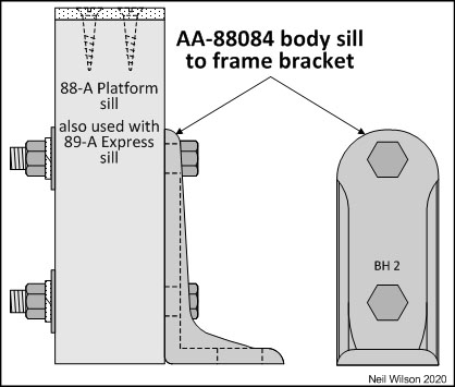
Body Sill to Frame Bracket
This bracket was used for the installation of Ford sold platforms as well as the 89-A and 242-A express bodies (two per body type). A corresponding AA-5077 frame to body-sill bracket was rivet to the frame. The change to use this bracket combination occurred in August 1928 (approximately).
These brackets replaced both frame body stops as well as the front 88-A U-bolts and 89-A floor tie straps as the forward installation hardware. The 88-A Platform Installation Hardware Gallery shows detailed installation of bracket AA-88084. This bracket was bolted to the sides of each sill prior to painting. Frame bracket AA-5077 was riveted to each outside face of the frame prior to frame painting. When the body was mounted to the frame, the brackets were bolted together.
88-A Platform Related Parts
88-A Platform Wheel Carriers
Wheel carriers for the 88-A Platform were under body carriers and came in three different designs.
Detailed wheel carrier information is found under the AA chassis carrier information where Ford listed these parts.
88-A Platform Rear Fenders
Rear fenders were optional equipment for the 88-A Platform through July 12, 1929 as per the Ford Service Bulletins.
AA platform trucks equipped with rear fenders required a number of additional parts.
All of these parts were listed as AA chassis parts by Ford. Check out the AA chassis fender information page.
- rear fender brackets
- rear fender spacers
- long running boards
- corresponding long shields
88-A Platform Tail Lamp Supports
Tail lamp supports were initially installed on the platform body and later they were attached to the frame.
Supports were listed as A and AA chassis parts by Ford. Check out the AA chassis electrical system information page.
88-A Platform Parts Listing
| # | Part | Part Description |
|---|---|---|
| Neil Wilson 2022 | ||
| 1 | AA-8800? | Platform Body Assembly d1, d2, and d3 (includes sill assemblies, support structure, cargo floor) |
| 88-A Platform Floor Sill Assembly | ||
| 2 | AA-88030 | d1 Sill (floor side) assembly (1-7/8 to 1-15/16 x 5-1/2 x 100) (for 1-1/8” Angles) 12/27—er/28 |
| d2 Sill (floor side) assembly (1-3/4 to 1-15/16 x 5-1/2 x 100) (for 3-9/16” Angles and Body Stops) er/28—6/28 | ||
| d3 Sill (floor side) assembly (1-3/4 to 1-15/16 x 5-1/2 x 100) (for 3-9/16” Angles and Brackets) 7/28— 2/31 | ||
| *1 | AA-88062 | d1 Plate (sill to U-bolt) (1/8 x 1-7/8 x 4) (for 1-1/8” Angles) 12/27—er/28 |
| d2 Plate (sill to U-bolt) (3/16 x 1-3/4 x 4) | ||
| *1 | AA-88064 | Plate (sill to U-bolt & cross member) (3/16 x 1-3/4 x 5-7/8) with curled end to retain U-bolt |
| *1 | AA-88066 | Plate (sill to cross member) (3/16 x 1-3/4 x 4) |
| Standard Parts – plate to sill – attachment | ||
| x | #12 x 1-1/4 flat head slotted wood screw (2 per plate) | |
| *1 refer to Floor Sill Assembly for number of plates per body | ||
| 88-A Platform Floor Support Structure | ||
| 1 | AA-88090 | Member (floor side) 4 pocket assembly RH (was TT-12701-X) 12/27—er/28 |
| 1 | AA-88090-B | Member (floor side) 6 pocket assembly RH – er/28—2/31 |
| 1 | AA-88091 | Member (floor side) 4 pocket assembly LH (was TT-12702-X) 12/27—er/28 |
| 1 | AA-88091-B | Member (floor side) 6 pocket assembly LH – er/28—2/31 |
| x | AA-88240 | Pocket (side) (was TT-12732-X) number per body dependent on floor side member version |
| Standard Parts – side pockets to side member – attachment | ||
| x | 9/32 x ?/? round head rivet (15/32” head) 4 per pocket | |
| x | 9/32 x ?/? flat head rivet (1/2” head) 2 per pocket | |
| 1 | AA-88092 | d1 Member (floor cross) #1 assembly (with 1-1/8” Angle) 12/27—er/28 |
| d2 Member (floor cross) #1 assembly (with 3-9/16” Angle) er/28—2/31 | ||
| 1 | AA-88093 | d1 Member (floor cross) #2 assembly (with 1-1/8” Angle) 12/27—er/28 |
| d2 Member (floor cross) #2 assembly (with 3-9/16” Angle) er/28—2/31 | ||
| 1 | AA-88094 | d1 Member (floor cross) #3 assembly (with 1-1/8” Angle) 12/27—er/28 |
| d2 Member (floor cross) #3 assembly (with 3-9/16” Angle) (without rear fender cutout) er/28 | ||
| d3 Member (floor cross) #3 assembly (with 3-9/16” Angle) (with rear fender cutout) er/28—2/31 | ||
| 1 | AA-88095 | d1 Member (floor cross) #4 assembly (with 1-1/8” Angle) 12/27—er/28 |
| d2 Member (floor cross) #4 assembly (with 3-9/16” Angle) (without rear fender cutout) er/28 | ||
| d3 Member (floor cross) #4 assembly (with 3-9/16” Angle) (with rear fender cutout) er/28—2/31 | ||
| 1 | AA-88096 | d1 Member (floor cross) #5 assembly (with 1-1/8” Angle) (tail light on body – 4 holes) 12/27—er/28 |
| d2 Member (floor cross) #5 assembly (with 3-9/16” Angle) (tail light on body – 3 holes) er/28—7/28 | ||
| d3 Member (floor cross) #5 assembly (with 3-9/16” Angle) (tail light on chassis) 7/27—2/31 | ||
| Standard Parts – Floor cross member #1-5 to side member – attachment | ||
| 30 | 1/4 x ?/? wagon head rivet (9/16” head) | |
| 1 | AA-88097 | d1 Member (floor cross) 3 pocket #6 assembly (with 4 bolt Reinforcement) 12/27—er/28 |
| d2 Member (floor cross) 3 pocket #6 assembly (with 3 bolt Reinforcement) er/28—md/28 | ||
| d3 Member (floor cross) 3 pocket #6 assembly (with locking stake pocket) md/28 | ||
| 1 | AA-88097-B | Member (floor cross) 4 pocket #6 assembly – md/28—2/31 |
| Standard Parts – Floor cross member #6 to side member – attachment | ||
| 4 | 1/4 x ?/? wagon head rivet (9/16” head) | |
| 1 | AA-88186 | d1 Support (floor board) on cross member #6 with 3 pockets |
| d2 Support (floor board) on cross member #6 with 4 pockets | ||
| Standard Parts – Floor Board Support to cross member #6 – attachment | ||
| 2 | 9/32 x ?/? round head rivet (15/32” head) insert from inside | |
| 4 | AA-88074 | Reinforcement (floor corner) |
| Standard Parts – Floor Corner Reinforcements to side members and cross members – attachment | ||
| 24 | 1/4 x ?/? wagon head rivet (9/16” head) on side member | |
| 24 | 9/32 x ?/? round head rivet (15/32” head) on cross member | |
| 5 | AA-88060 | d1 Angle (side sill to cross member) RH (1-1/8”) 12/27—er/28 |
| d2 Angle (side sill to cross member) RH (3-9/16”) (without hole for tie down) er/28—er/29 | ||
| d3 Angle (side sill to cross member) RH (3-9/16”) (with hole for tie down) er/29—2/31 | ||
| 5 | AA-88061 | d1 Angle (side sill to cross member) LH (1-1/8”) 12/27—er/28 |
| d2 Angle (side sill to cross member) LH (3-9/16”) (without hole for tie down) er/28—er/29 | ||
| d3 Angle (side sill to cross member) LH (3-9/16”) (with hole for tie down) er/29—2/31 | ||
| Standard Parts – Angles to cross member – attachment | ||
| x | 9/32 x ?/? round head rivet (15/32” head) (1-1/8” Angle – x20; 3-9/16” Angle – x30) | |
| Standard Parts – Angles to side sill – attachment | ||
| x | *S1 | 5/16-18 x 2-1/2 carriage bolt (1-1/8” Angle – x20; 3-9/16” Angle – x30) |
| *S1 | 5/16-18 (1/4 x 9/16) square nut (chamfered one side) | |
| *S1 | 5/16 (3/32 x 7/8) flat washer | |
| *S1 | 5/16 (3/32 x 23/32) lock washer | |
| 1 | AA-88140 | d1 Reinforcement (cross member #6 to side sill) RH (4 bolt type) 12/27—er/28 |
| d2 Reinforcement (cross member #6 to side sill) RH (3 bolt type) er/28—2/31 | ||
| 1 | AA-88141 | d1 Reinforcement (cross member #6 to side sill) LH (4 bolt type) 12/27—er/28 |
| d2 Reinforcement (cross member #6 to side sill) LH (3 bolt type) er/28—2/31 | ||
| Standard Parts – Cross Member #6 Reinforcements to cross member #6 – attachment | ||
| 10 | 9/32 x ?/? round head rivet (15/32” head) | |
| Standard Parts – Cross Member #6 Reinforcements to side sill – attachment | ||
| x | *S2 | 5/16-18 x 2-1/2 carriage bolt (Reinforcement d1 – x8; Reinforcement d2 – x6) |
| *S2 | 5/16-18 (1/4 x 9/16) square nut (chamfered one side) | |
| *S2 | 5/16 (3/32 x 23/32) lock washer | |
| 2 | AA-88235 | Pocket (stake) cross member #1 (was TT-12727-X) |
| 3 | AA-88237 | Pocket (stake) cross member #6 (was TT-12728-X) |
| 1 | AA-88239 | Pocket (locking stake) cross member #6 – md/28—2/31 |
| Standard Parts – Pockets to cross members – attachment | ||
| x | 9/32 x ?/? round head rivet (15/32” head) – 3-pocket #6 cross member (x12); 4-pocket #6 cross member (x16) | |
| 1 | AA-88075 | Brace (cross member #3 & #4 to rear fender) RH |
| 1 | AA-88076 | Brace (cross member #3 & #4 to rear fender) LH |
| Standard Parts – Brace to cross member – attachment | ||
| 8 | 1/4 x ?/? round head rivet (7/16” head) | |
| *S1—S2 – refer to Platform Summary Gallery | ||
| 88-A Platform Cargo Floor | ||
| 12/27—er/28 – all boards (1-1/4 x 7-1/4 x 98-1/2) | ||
| 7 | AA-88165 | Board (floor) center |
| 1 | AA-88172 | Board (floor) side RH (no recess for bolt above fender) |
| 1 | AA-88173 | Board (floor) side LH (no recess for bolt above fender) |
| er/28-2/31 – all boards (1-1/4 x 7-1/4 x 98-1/2) | ||
| 5 | AA-88165 | Board (floor) center |
| 1 | AA-88174 | Board (floor) side center RH (recess for bolt above fender) |
| 1 | AA-88175 | Board (floor) side center LH (recess for bolt above fender) |
| 1 | AA-88172 | Board (floor) side RH (recess for bolt above fender) |
| 1 | AA-88173 | Board (floor) side LH (recess for bolt above fender) |
| 8 | AA-88180 | Strip (floor skid) |
| Standard Parts – Floor to support structure assembly – attachment | ||
| 12/27—er/28 (no recess for bolt above fender) | ||
| 98 | *F1 | 5/16-18 x 2 (7/64 x 3/4 head) carriage bolt |
| 98 | *F1—F2 | 5/16-18 (1/4 x 9/16) square nut (chamfered 1 side) |
| 98 | *F1—F2 | 5/16 (3/32 x 23/32) lock washer |
| 48 | *F1—F2 | 5/16 (3/32 x 1 x 1) square washer (1 corner curled) |
| er/28-2/31 (recess for bolt above fender) | ||
| 96 | *F1—F2 | 5/16-18 x 2 (7/64 x 3/4 head) carriage bolt |
| 2 | *F3 | 5/16-18 x 1-3/8 (7/64 x 3/4 head) carriage bolt |
| 98 | *F1—F3 | 5/16-18 (1/4 x 9/16) square nut (chamfered 1 side) |
| 98 | *F1—F3 | 5/16 (3/32 x 23/32) lock washer |
| 48 | *F1—F3 | 5/16 (3/32 x 1 x 1) square washer (1 corner curled) |
| *F1—F3 – refer to the Cargo Floor Gallery | ||
| 88-A Platform Installation Hardware (for all versions – 1—8) | ||
| AA-88048 | Bolt (floor to chassis frame “U”) long (d1, d2, or d3) | |
| AA-88057 | Bolt (floor to chassis frame “U”) medium (d1, d2, or d3) | |
| AA-88050 | Bolt (floor to chassis frame “U”) short (d1 w/long bar and wood frame spacer; d2 and d3 w/short bar and sleeve spacer) | |
| AA-88052 | Bar (U-bolt cross) long (1/2 x 1-1/8 x 4-1/4) | |
| AA-88054 | Bar (U-bolt cross) short (1/2 x 1-1/8 x 3-7/8) 7/28—2/31 | |
| Standard Parts – Bar to U-bolt & frame – attachment (2 nuts per U-bolt) | ||
| 1/2-13 (1/2 x 7/8) hex nut (chamfered 1 side) | ||
| 1/2 (1/8 x 7/8) lock washer | ||
| 2 | AA-88084 | Bracket (body sill ) to frame bracket |
| Standard Parts – Bracket to sill – attachment | ||
| 4 | 3/8-24 x 2-3/4 (9/32 x 9/16) hex head bolt | |
| 4 | 3/8-24 (5/16 x 9/16) hex nut (chamfered 1 side) | |
| 4 | 3/8 (1/16 x 1) flat washer | |
| 4 | 3/8 (3/32 x 21/32) lock washer | |
| 2 | AA- 5077 | Bracket (frame) to body sill bracket |
| Standard Parts – Bracket to bracket – attachment | ||
| 2 | A-21237 | 1/2-20 x 1-1/2 (3/8 x 3/4) hex head bolt |
| 2 | A-21845 | 1/2-20 (7/16 x 3/4) hex nut |
| 2 | A-22330 | 1/2 (1/8 x 7/8) lock washer |
| AAAAAAAAA | ||
Page Contents