
2023/12/01 update
Page Contents
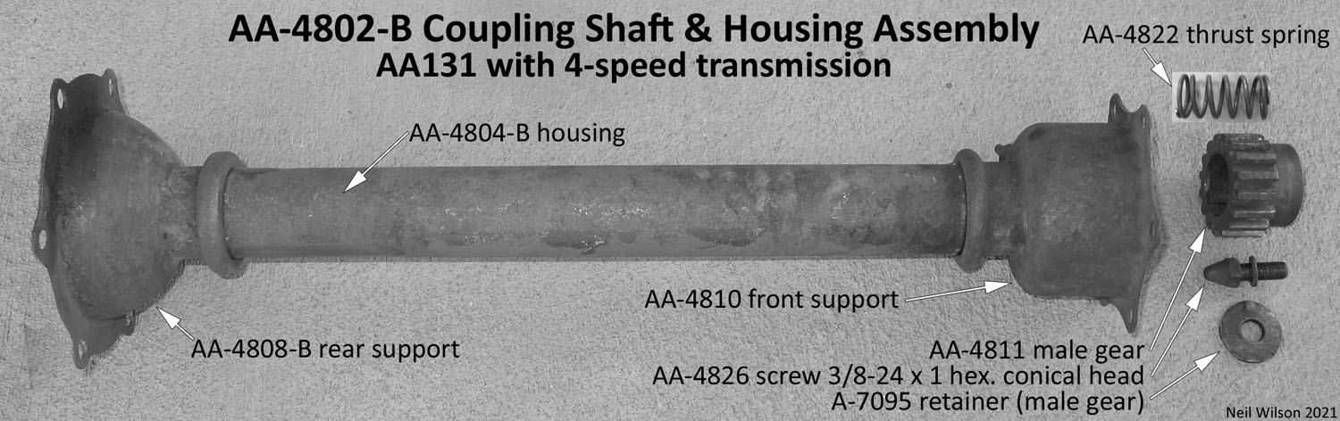
Description – AA-4802-B/C Coupling Shaft Assemblies – AA’s with 4-speed
Links – Coupling shaft for AA131/AA157 AA’s with a 4-speed transmission
These two production assemblies were the same except for the length of the coupling shaft and corresponding housing. They were a simpler design as compared to the prior assembly used for AA’s with the A-chassis 3-speed transmission. These assemblies may have been replaced due to repairs over the years. Refer to Repair Coupling Shaft for identification.
Assembly AA-4802-B was used for AA131‘s with the 4-speed transmission starting September 1929 through the end of production in December 1932.
Assembly AA-4802-C was used for all AA157‘s which came with the 4-speed transmission as standard.
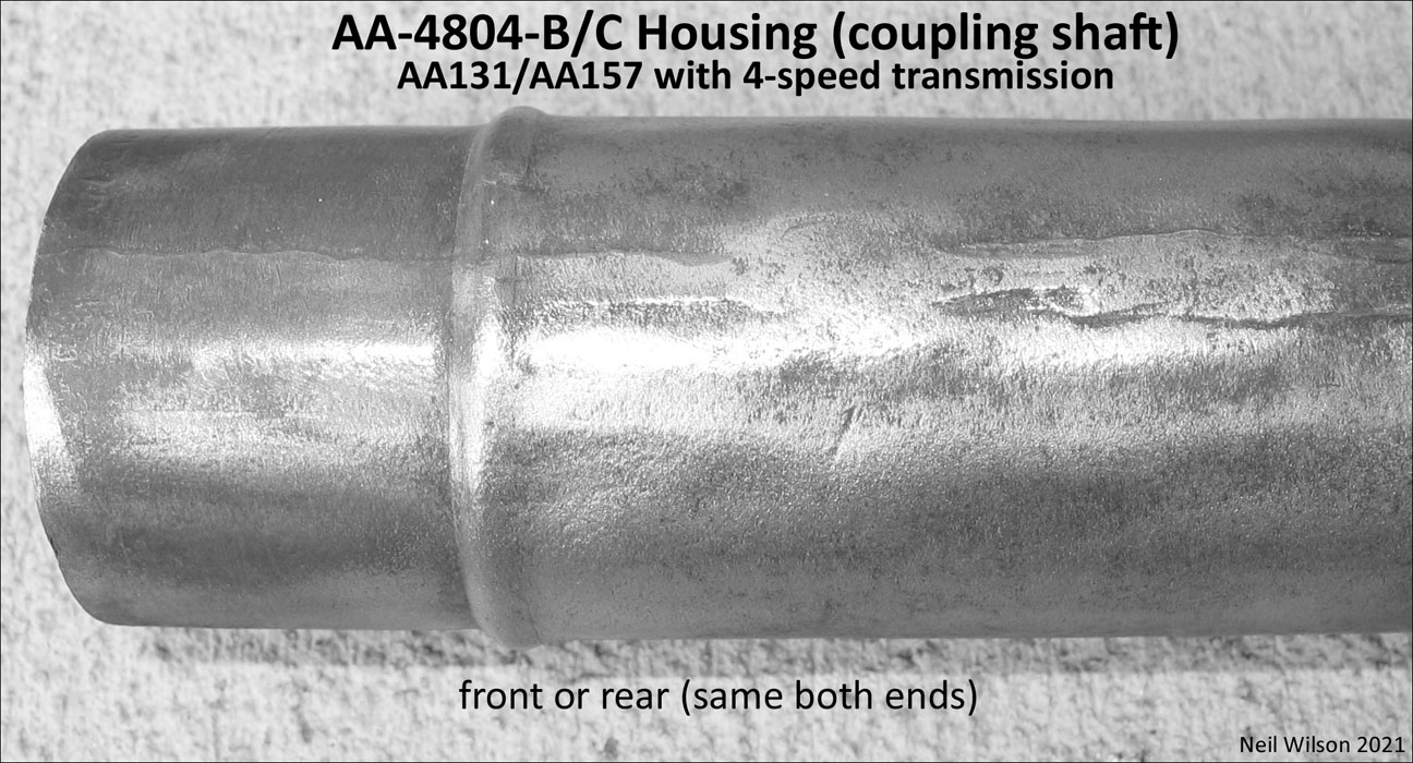
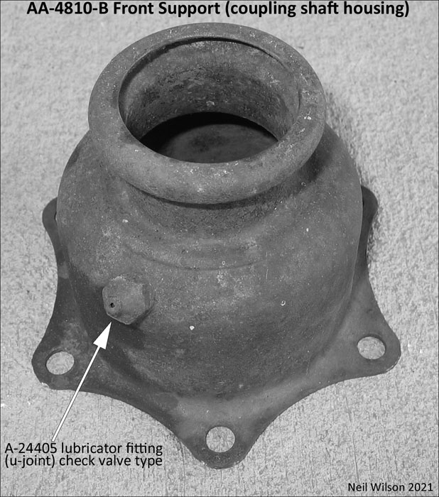
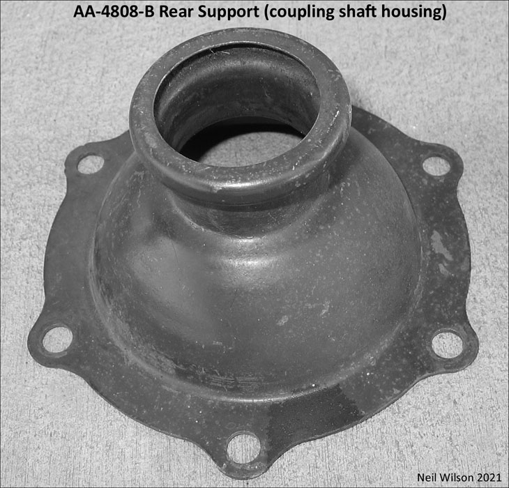
The housings and the front/rear housing supports were simply coverings to enclose the shaft and retain grease.
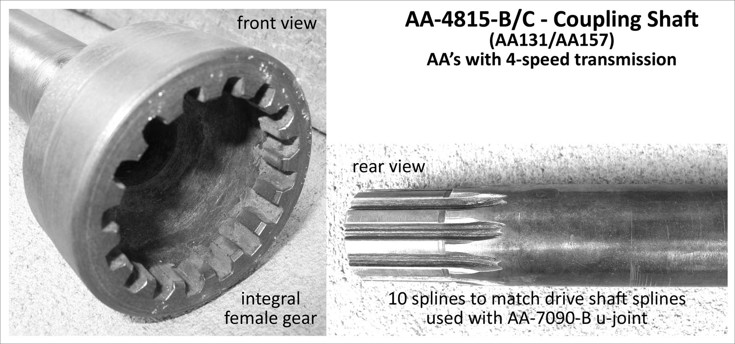
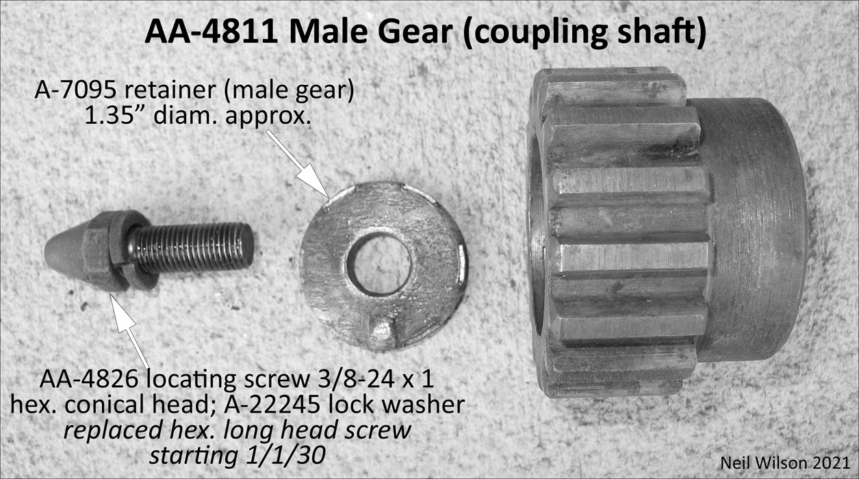
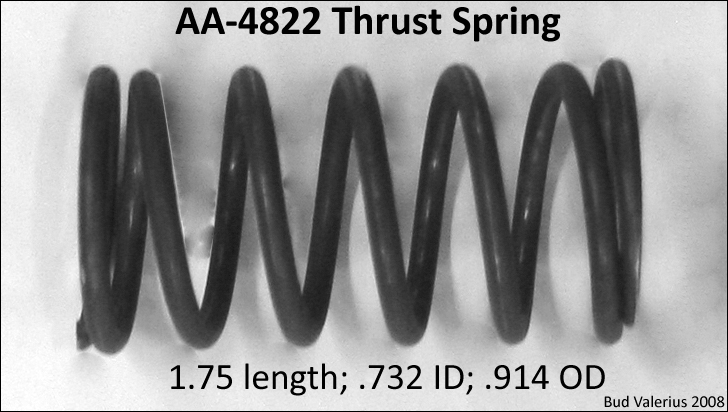
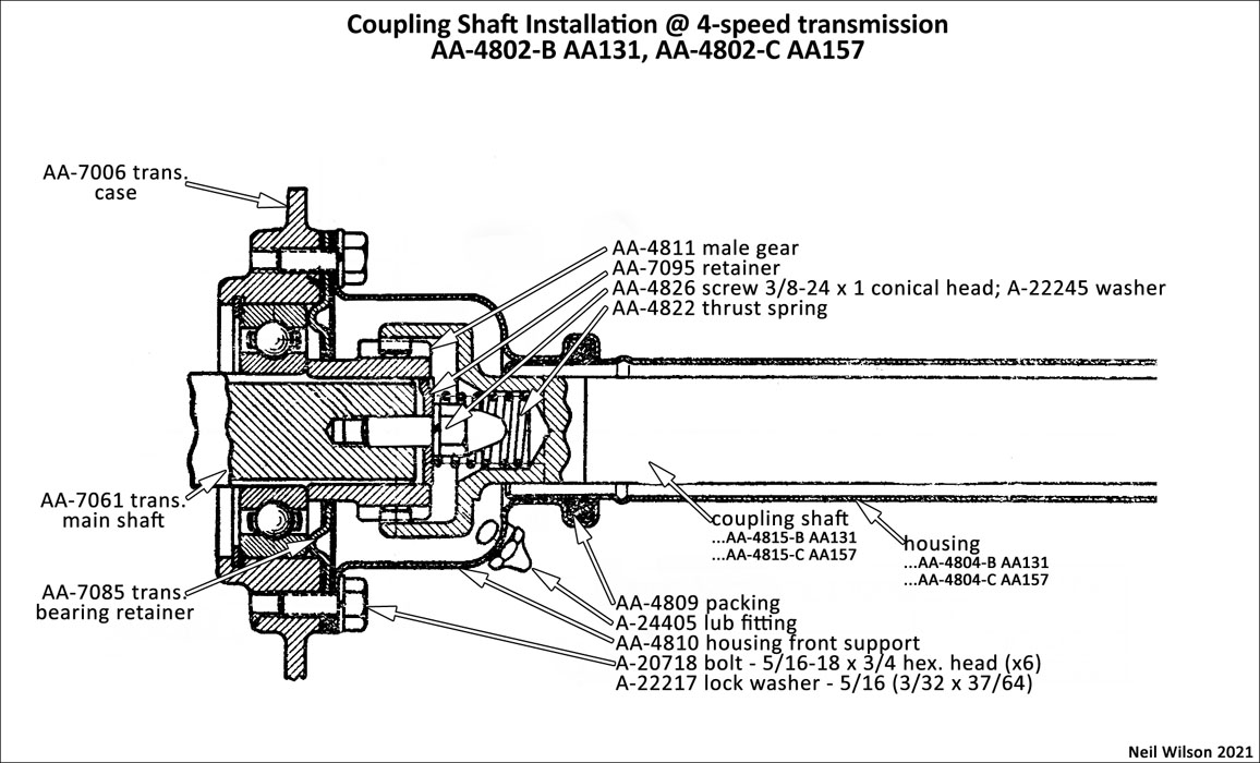
The coupling shafts of the assemblies had an integral female gear at the front. This gear meshed with a male gear attached to the 4-speed transmission main shaft with a retainer and conical head locating screw. There was a shaft thrust spring which was centered by the locating screw.
The rear of these coupling shafts had 10 splines which matched the drive shaft splines. Consequently, the new AA-7090-B u-joint had matching splines for the front knuckle.
Refer to the parts table and parts gallery below.
Note – Table part finish codes are found in “Part Description” column following the description. The code meanings are the same as used in the RGJS – (bst)-black satin; (bsg)-black semi-gloss; (bg)-black gloss; (c)-cadmium; (g)-Ford engine green; (r)-raven; (u)-unfinished; (z)-Zink
Gallery – AA-4808-B/C Coupling Shaft Assembly (with 4-speed transmission)
Installations – AA-4802-B/C Coupling Shaft Assemblies – AA’s with 4-speed
These assemblies were installed through the rear side of the #3 frame cross member. Consequently, removal required the rear of the AA frame to be blocked up and the rear axle to be disconnected allowing it to be move back enough so that the drive shaft pulled out of the u-joint connected to the rear of the coupling shaft.
Once these tasks were accomplished, the coupling shaft assembly could be disconnected from the transmission and removed through the back side of the #3 frame cross member.
Additional parts not covered by the coupling shaft parts group are shown in the table below. Following the table is a drawing of the installation @ the 4-speed trans.
Note – Some of the Ford drawings show the heads of bolts on the back side of the #3 frame cross member. This makes cotter pin installation/removal difficult. Other drawings show the opposite. This makes cotter pin installation easier. Original Ford assembly line bolt installation direction is not known.
Installation @ 4-speed transmission (AA-4802-B/C)
| Coupling Shaft Assemblies (AA’s with 4-speed trans.) – installation @ transmission | ||
|---|---|---|
| parts not covered by the coupling shaft parts group table | ||
| # | Part | Part Description (finish code) |
| Neil Wilson 2021 | ||
| 1 | AA-7085 | Retainer (trans. main shaft bearing) (g) |
| 2 | AA-7086 | Gasket (trans. main shaft bearing retainer) on each side of retainer |
| 1 | AA-4810 | Front support (coupling shaft housing) (bsg) |
| fasteners – coupling shaft front support to trans. bearing retainer and trans. | ||
| 6 | A-20718 bolt – 5/16-18 x 3/4 hex. head (u) | |
| 6 | A-22217 lock washer – 5/16 (3/32 x 37/64) (u) | |
| 1 | AA-4811 | Coupling gear (male) |
| 1 | AA-7095 | Retainer (male gear) – 1.35″ diam. approx. (u) |
| 1 | same retainer used for rear u-joint; trans. part group number | |
| fasteners – male gear to trans. main shaft | ||
| 1 | AA-???? locating screw – 3/8-24 x 1 hex. long head (u) thru 12/29 | |
| 1 | AA-4826 locating screw – 3/8-24 x 1 hex. conical head (u) starting 1/1/30 | |
| 1 | A-22245 lock washer – 3/8 (.401-.411 3/32 x 21/32) (u) | |
| AAAAAAAAA | aaaaaaaaaaaaaaaaaaaa aaaaaaaaaaaaaaaaaaaa aaaaaaaaaaaaaaaaaaaa aaaaaaa | |
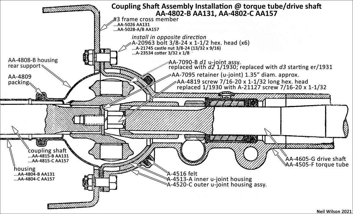
Installation @ Torque Tube (AA-4802-B/C)
| Coupling Shaft Assemblies (AA’s with 4-speed trans.) – installation @ torque tube | ||
|---|---|---|
| parts not covered by the coupling shaft parts group table | ||
| # | Part | Part Description (finish code) |
| Neil Wilson 2021 | ||
| 1 | AA-7090-B d1 | U-Joint – rivet together – without collar-stop; not rebuildable – only for 1929 |
| 1 | AA-7090-B d2 | U-Joint – rivet together – with collar-stop; not rebuildable – Jan 1930 to er/1931 |
| 1 | AA-7090-B d3 | U-Joint – replaceable spider kit AA-7084 – starting er/1931 |
| 1 | AA-7095 | Retainer (u-joint front knuckle) 1.35″ diam. approx. |
| fasteners – u-joint to coupling shaft | ||
| 1 | AA-4819 screw 7/16-20 x 1-1/32 long hex. head (u) only for 1929 | |
| stop for the drive shaft; with AA-7090-B d1 u-joint | ||
| 1 | A-21127 screw 7/16-20 x 1-1/32 hex. head (u) starting 1/30 | |
| used with AA-7090-B d2-d3 u-joints | ||
| 1 | A-22??? lock washer 7/16 ?????? (u) | |
| 1 | ..A-4513-A | Cap (u-joint housing – inner) |
| 2 | ..A-4515 | Gasket (u-joint housing inner cap) on each bolt flange |
| 2 | ..A-4516 | Felt (u-joint housing outer cap assembly) |
| 1 | ..A-4520 | Cap assembly (u-joint housing – outer) (bsg) |
| fasteners – cap assembly upper to lower | ||
| 2 | A-20905 screw 3/8-24 x 1 hex. head (u) | |
| 2 | A-21741 nut 3/8-24 (21/64 x 9/16) hex. (u) | |
| 2 | A-22245 lock washer 3/8 (.401-.411 3/32 x 21/32) (u) | |
| 1 | AA-4808-B | Rear support (coupling shaft housing) (bsg) |
| fasteners – caps to rear support and #3 frame cross member | ||
| 6 | A-20963 bolt 3/8-24 x 1-1/2 hex. head (u) | |
| 6 | A-21745 castle nut 3/8-24 (13/32 x 9/16) (u) | |
| 6 | A-23534 cotter 3/32 x 1/8 (u) | |
| AAAAAAAAA | aaaaaaaaaaaaaaaaaaaa aaaaaaaaaaaaaaaaaaaa aaaaaaaaaaaaaaaaaaaa aaaaaaa | |
Page Contents