
2023/12/01 update
Page Contents
Description – AA-4802-D/E Repair Coupling Shaft Assemblies – AA’s with 4-speed
Links – Repair coupling shaft for AA131/AA157 AA’s with a 4-speed transmission
In July 1932, Ford announced the release of repair AA coupling shaft assemblies for those AA’s with a 4-speed transmission. These assemblies were offered through service as improved replacements.
Repair coupling shaft AA-4802-D was for the AA131 and AA-4802-E was for the AA157. Unlike the production coupling shaft assemblies, these repair assemblies could be removed/installed without disturbing the rear axle. This reduced the labor involved for servicing the coupling shaft, u-joints, transmission, and clutch. The BB-chassis had the same design of coupling shaft assemblies.
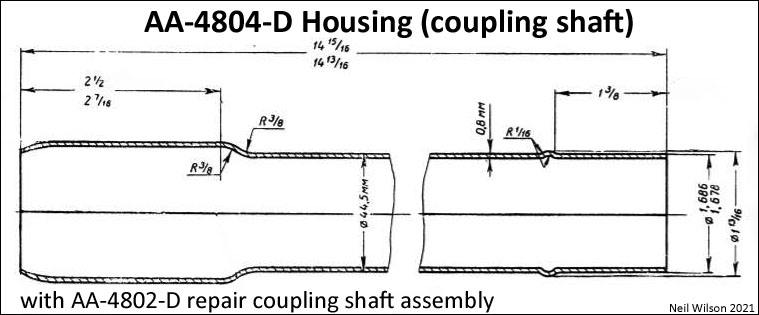
None of the parts for these repair coupling shaft assemblies (including the shaft, shaft housing, front and rear housing supports, etc.) were the same as the production assemblies. The parts could not be intermixed.
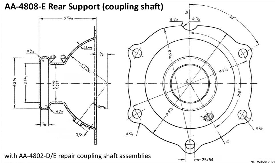
The coupling shaft housing rear support was installed on the front side of the #3 frame cross member rather than being inserted from the rear like the production rear supports. It was 11/32” (.345”) shorter in length than the production rear support. This rear support used five of the six bolts for installation @ the torque tube. When a coupling shaft assembly was removed, the bolt at the twelve-o’clock position was not removed so that the rear axle was held in place while the AA was being serviced.
The coupling shafts of these assemblies had 10 splines at the front and rear which matched the splines of the drive shaft.
There were a thrust spring washer and a thrust spring installed over the front splines of the coupling shaft to handle end-play.
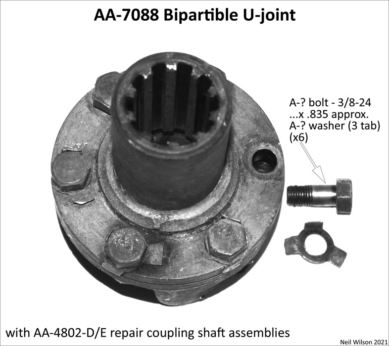
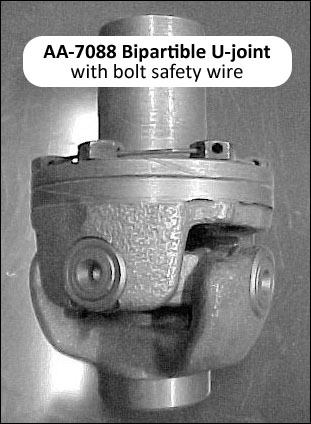
For installation of these repair assemblies at the 4-speed transmission, a bipartible (i.e. bolt together) AA-7088 u-joint replace the production AA-4811 male gear.
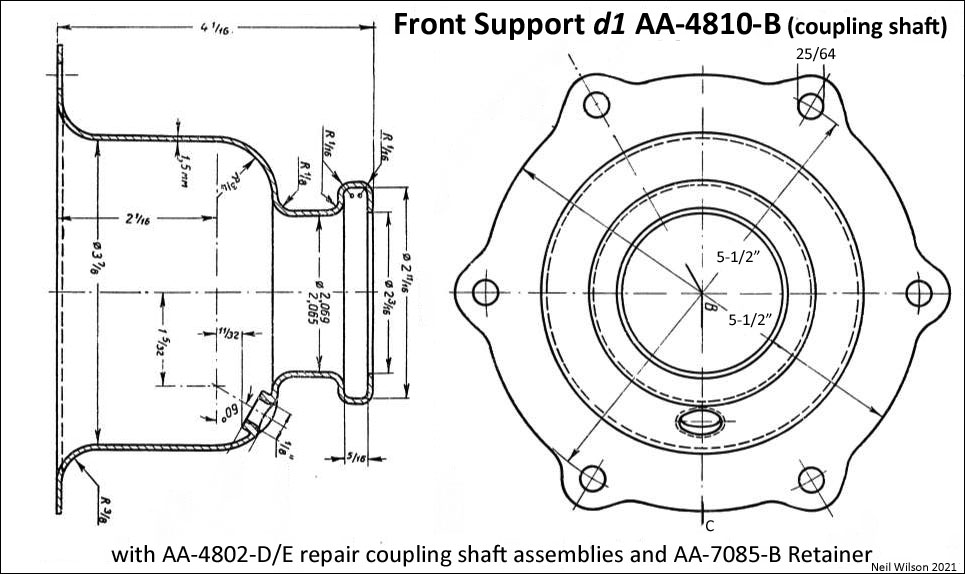
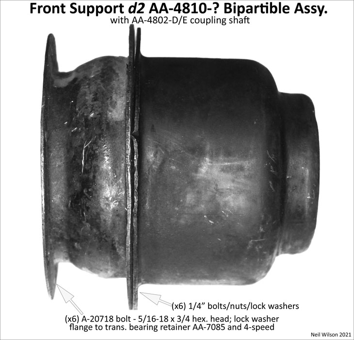
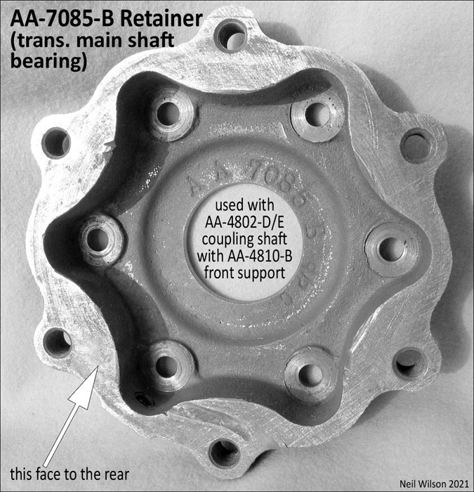
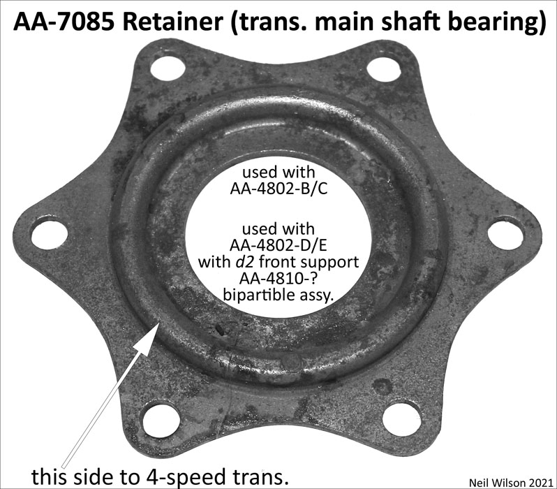
The initial housing front support AA-4810-B used cast-steel AA-7085-B transmission bearing retainer for connection to the 4-speed transmission. A stamped-steel, bipartible housing front support was introduced (date unknown). This front support used the production AA-7085 transmission bearing retainer for connection to the 4-speed transmission.
Note – Table part finish codes are found in “Part Description” column following the description. The code meanings are the same as used in the RGJS – (bst)-black satin; (bsg)-black semi-gloss; (bg)-black gloss; (c)-cadmium; (g)-Ford engine green; (r)-raven; (u)-unfinished; (z)-Zink
Gallery – AA-4808-D/E Repair Coupling Shaft Assemblies (with 4-speed transmission)
Installations – AA-4802-D/E Repair Coupling Shaft Assemblies – AA’s with 4-speed
Coupling shaft assemblies AA-4802-D/E were installed between the 4-speed transmission and the torque tube.
Ford made a change to the installation parts at the 4-speed transmission (date unknown). Due to this change, the installation at the 4-speed has two versions. See @ 4-speed installation.
There was only one version for the installation of these coupling shaft assemblies at the torque tube. See @ torque tube installation.
Removal/Installation – based on Ford 1932 Service Bulletin, the following are the removal steps for the assemblies with the initial d1 housing-front-support. The installation steps were the reverse steps.
- Remove bolts (on #3 frame cross member) – all but top bolt – five bolts/castle nuts/cotters
- Remove bolts (front coupling shaft support to trans. main shaft bearing retainer) – six bolts/washers
- Slide front support (rearward on coupling shaft housing 6”)
- Remove bolts (bipartible u-joint rear-knuckle) – six bolts/3-tab-washers
- Push u-joint rear-knuckle-half rearward (compressing thrust spring)
- Pull front end of assembly down to clear transmission rear bearing retainer (while thrust spring is compressed)
- Pull assembly forward until rear u-joint is free of drive shaft
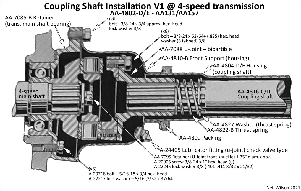
Installations @ 4-speed transmission (AA-4802-D/E)
Installation Version 4sV1 – This installation (at the 4-speed) included d1 front support AA-4810-B and cast steel AA-7085-B transmission main shaft bearing retainer.
Installation Version 4sV2 – This installation (at the 4-speed trans.) included d2 front support AA-4810-?. It was a stamped-steel, bipartible assembly (design-date/part not known). It was used with the AA-7085 standard transmission main shaft bearing retainer.
Installation 4sV1
Additional Installation 4sV1 Parts Table @ 4-speed transmission
| Repair Coupling Shaft Assy. (AA’s with 4-speed trans.) – installation V1 @ 4-speed | ||
|---|---|---|
| parts not covered by the coupling shaft parts group table | ||
| # | Part | Part Description (finish code) |
| Neil Wilson 2021 | ||
| 1 | AA-7086 | Gasket (trans. main shaft bearing retainer) |
| 1 | AA-7085-B | Retainer (trans. main shaft bearing) |
| fasteners – retainer to trans. | ||
| 6 | A-20718 bolt – 5/16-18 x 3/4 hex. head | |
| 6 | A-22217 lock washer – 5/16 (3/32 x 37/64)(u) | |
| 1 | AA-7088 | U-joint – bipartible |
| fasteners – bipartible u-joint | ||
| 6 | A-????? bolt – 3/8-24 x 53/64+ (.835) hex. head – if with tabbed washer | |
| 6 | A-????? washer (3 tabbed) 3/8(u) | |
| 1 | AA-7095 | Retainer (u-joint front knuckle) 1.35″ diam. approx. |
| fasteners – bipartible u-joint to transmission | ||
| 1 | A-20905 screw 3/8-24 x 1 hex. head (u) | |
| 1 | A-22245 lock washer 3/8 (.401-.411 3/32 x 21/32) (u) | |
| AAAAAAAAA | aaaaaaaaaaaaaaaaaaaa aaaaaaaaaaaaaaaaaaaa aaaaaaaaaaaaaaaaaaaa aaaaaaa | |
Installation 4sV2
Additional Installation 4sV2 Parts Table @ 4-speed transmission
| Repair Coupling Shaft Assy. (AA’s with 4-speed trans.) – installation V2 @ 4-speed | ||
|---|---|---|
| parts not covered by the coupling shaft parts group table | ||
| # | Part | Part Description (finish code) |
| Neil Wilson 2021 | ||
| 1 | AA-7085 | Retainer (trans. main shaft bearing) |
| 1 | AA-7086 | Gasket (trans. main shaft bearing retainer) retainer to trans. |
| 1 | AA-7088 | U-joint – bipartible |
| fasteners – bipartible u-joint | ||
| 6 | A-????? bolt – 3/8-24 x 53/64+ (.835) hex. head – if with tabbed washer | |
| 6 | A-????? washer (3 tabbed) 3/8(u) | |
| 1 | AA-7095 | Retainer (u-joint front knuckle) 1.35″ diam. approx. |
| fasteners – bipartible u-joint to transmission | ||
| 1 | A-20905 screw 3/8-24 x 1 hex. head (u) | |
| 1 | A-22245 lock washer 3/8 (.401-.411 3/32 x 21/32) (u) | |
| AAAAAAAAA | aaaaaaaaaaaaaaaaaaaa aaaaaaaaaaaaaaaaaaaa aaaaaaaaaaaaaaaaaaaa aaaaaaa | |
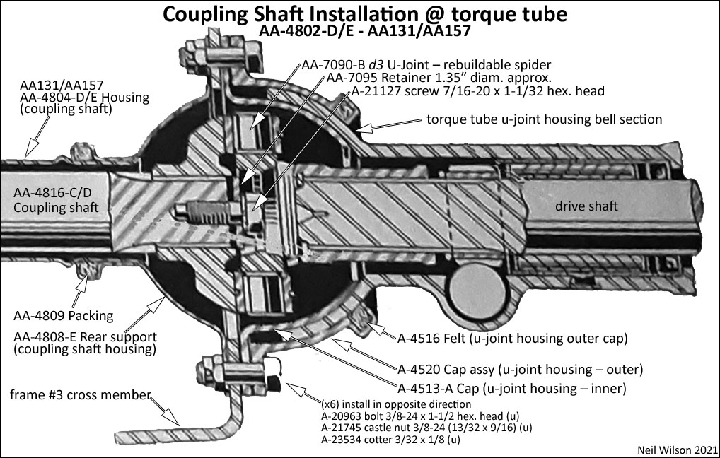
Installation @ Torque Tube (AA-4802-D/E)
This installation was basically the same as the installation for the AA-4802-B/C coupling shaft.
However, the rear support was installed on the front side of the #3 frame cross member allowing it to be removed without disturbing the u-joint housing cab assembly connection.
The additional installation parts are shown in the table below. A drawing of this installation follows.
Additional Installation Parts Table @ torque tube
| Repair Coupling Shaft Assemblies (AA’s with 4-speed trans.) – installation @ torque tube | ||
|---|---|---|
| parts not covered by the coupling shaft parts group table | ||
| # | Part | Part Description (finish code) |
| Neil Wilson 2021 | ||
| 1 | AA-7090-B d3 | U-joint – rebuildable spider – started er/1931 |
| 1 | AA-7095 | Retainer (u-joint front knuckle) 1.35″ diam. approx. |
| fasteners – u-Joint to coupling shaft | ||
| 1 | A-21127 screw 7/16-20 x 1-1/32 hex. head (u) | |
| 1 | A-22??? lock washer 7/16 ?????? (u) | |
| 1 | ..A-4513-A | Cap (u-joint housing – inner) |
| 2 | ..A-4515 | Gasket (u-joint housing inner cap) |
| 2 | ..A-4516 | Felt (u-joint housing outer cap) |
| 1 | ..A-4520 | Cap assembly (u-joint housing – outer) (bsg) |
| fasteners – cap assembly upper to lower | ||
| 2 | A-20905 screw 3/8-24 x 1 hex. head (u) | |
| 2 | A-21741 nut 3/8-24 (21/64 x 9/16) hex. (u) | |
| 2 | A-22245 lock washer 3/8 (.401-.411 3/32 x 21/32) (u) | |
| fasteners – caps to rear support and #3 frame cross member | ||
| 6 | A-20963 bolt 3/8-24 x 1-1/2 hex. head (u) | |
| 6 | A-21745 castle nut 3/8-24 (13/32 x 9/16) (u) | |
| 6 | A-23534 cotter 3/32 x 1/8 (u) | |
| AAAAAAAAA | aaaaaaaaaaaaaaaaaaaa aaaaaaaaaaaaaaaaaaaa aaaaaaaaaaaaaaaaaaaa aaaaaaa | |
Page Contents