
2023/12/01 update
Page Contents
Overview – Front Spring AA-5310 AA131 1927—1929
The following article covers the front spring assembly and related installation parts used for the AA-chassis from 12/27—12/29. The photo below highlights the spring assembly. It was a 12-leaf assembly AA-5310. Leaves 1—11 were unique to the AA-chassis. Leaf #12 (top leaf) was the same as the A-chassis front spring leaf #10.
The spring assembly had a 1-3/4″ width that was the same width as the A-chassis front spring assembly. It included two AA-chassis spring clamps and two A-chassis front spring bushings.
Assembly-line-spraying is noted in this article. The assembled front end (with front spring) was installed in the AA-chassis prior to this step. This chassis black pyroxylin spraying step is explained in the “Model A & AA Ford Paint & Finish Guide” (current edition 4 available from MAFCA).
Installation parts for assembly AA-5310 included:
- Starting Crank Bearing – A-chassis part
- Front Spring Clips – AA-chassis parts
- Front Spring Clip Bar – AA-chassis part
- Front Spring Hangers and Bars – A-chassis parts
Note – For AA-vehicles found today, this AA-5310 spring is frequently in a broken and/or modified condition. It is hoped that this article provides the detail needed for restorers to know what to look for.
Note – This article references the Restoration Guidelines and Judging Standards as RGJS which is available via MAFCA or MARC national clubs).

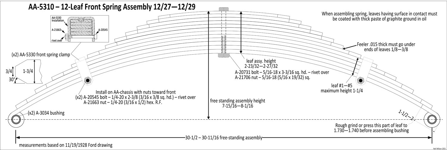
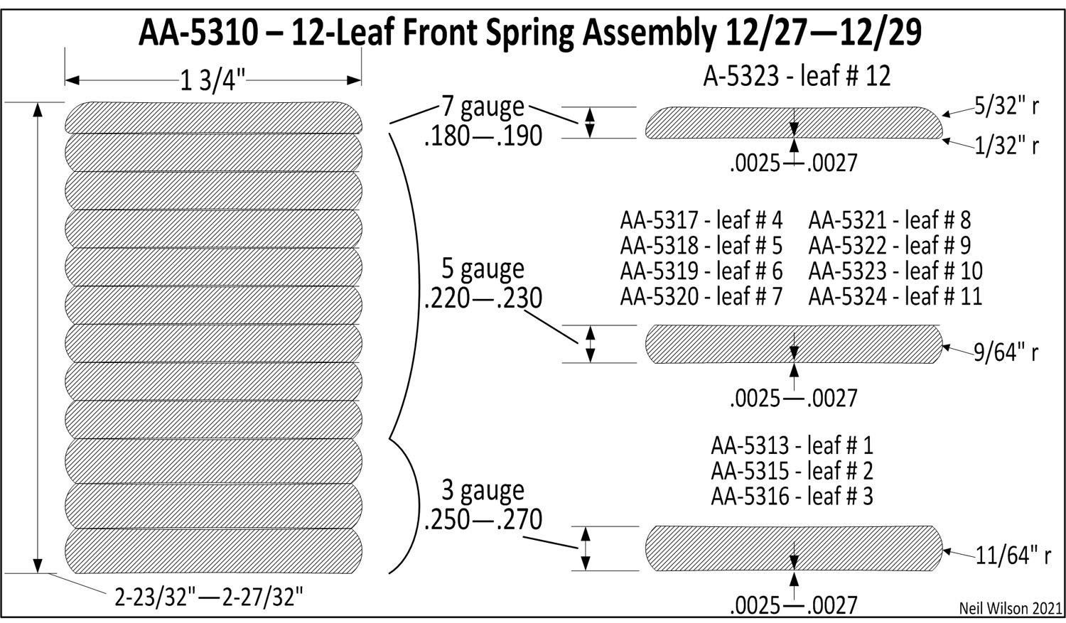
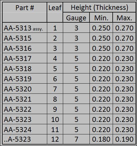
Front Spring Leaf Stack – AA-5310
This 12-leaf spring stack was 2-23/32—2-27/32 in height. This resulted in leaves which could be seen below the face of the front cross member.
Except the #12 leaf (i.e. top leaf), all leaves were unique to the AA-chassis (leaf #12 was the A-chassis #10 leaf). The free-standing height of the assembled leaves was 7-15/16—8-1/16 at the spring eyes center lines.
The leaf stack was held together with an unfinished center bolt and nut:
- A-20731 bolt – 5/16-18 x 3-3/16 sq. hd. – rivet over end after installation
- A-21706 nut – 5/16-18 (5/16 x 19/32) sq.
The drawings following provide details regarding the makeup of the individual leaves and assembly parts.
Front Spring Assembly Details – AA-5310
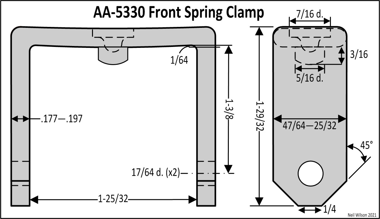
Front Spring Clamps – AA-5330
The stamped steel AA-5330 spring clamps were designed to fit the 1.27″ height of the #1—#5 spring leaf stack of the spring assembly. See the AA-5310 highlights above and the clamp detail below.
The #5 leaf had a hole on each end to accept the 5/16″ round boss punched into the top-undersides of the clamps.
The clamp installation bolt head was to the rear to allow its removal during service. The hardware was:
- A-20545 bolt – 1/4-20 x 2-3/8 (3/16 x 3/8 sq. hd.) rivet over end after installation
- A-21663 nut – 1/4-20 (3/16 x 1/2) hex. R.F.
The bolts had a thread length of 11/16″. But bolt ends were specified as “rivet over” (see AA-5310 highlights). So, salvaging originals is a challenge.
Clamps with “Ford” script stamped across the top-side of 3/4″ width have been found. This was likely early 1928 only.
Clamps were installed as part of the spring assembly. The assembly was a black satin finish.
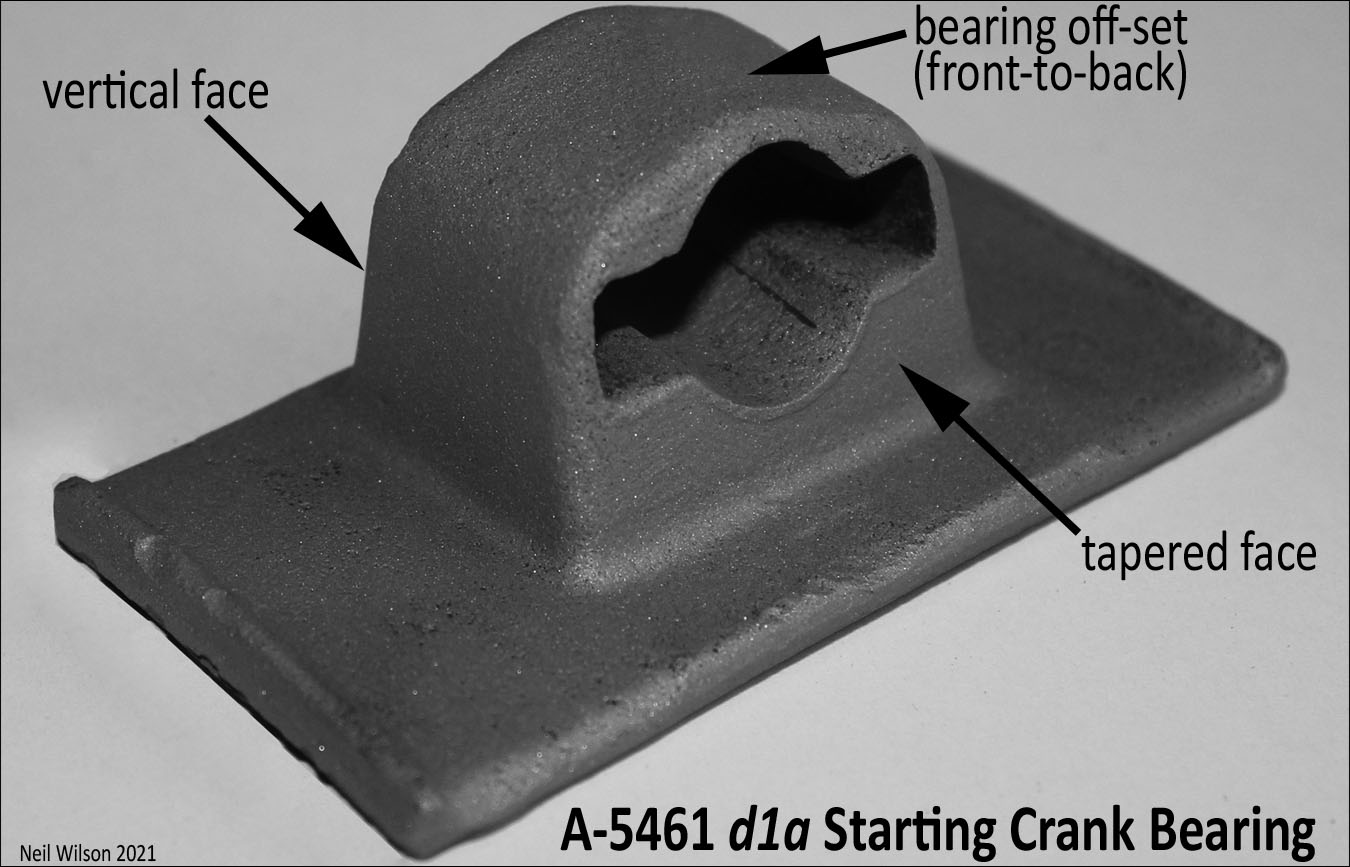
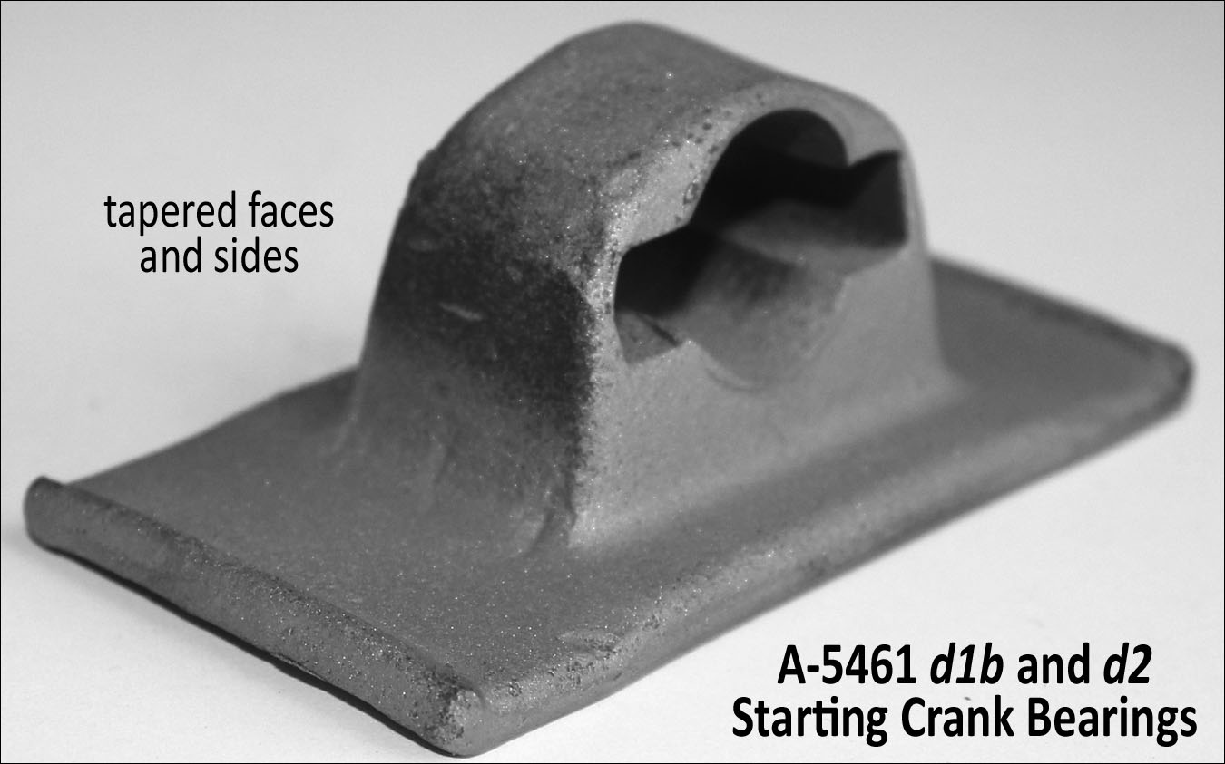
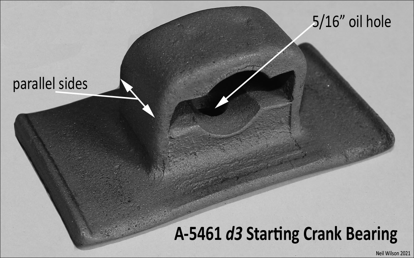
Starting Crank Bearing – A-5461
This forged steel A-5461 starting crank bearing had flat flanges on each side of the bearing to accept square-style spring clips. Designs were:
d1a – Smooth-bottomed – 12/27—2/28 – This bearing had a vertical and a tapered face. The bearing was off-set (front-to-back). An example is shown below.
d1b – Smooth-bottomed – early 1928 – This bearing had tapered faces and sides. It was centered (front-to-back). Refer to the A-5461 d1b and d2 image below.
d2 – Bottom with two 1/4″ radius bosses – starting as early as January 1928 – It looked like the d1b bearing otherwise. Refer to the A-5461 d1b and d2 image below.
d3 – Bottom with two 1/4″ radius bosses and a 5/16″ oil hole – starting June 1929 – An example is shown below. This bearing has been found with the manufactures trade mark and 5461 on the bottom side. The bearing faces and sides were vertical making the top wider than the d1—d2 designs.
The bearing was a gloss black finish before assembly-line-spraying.
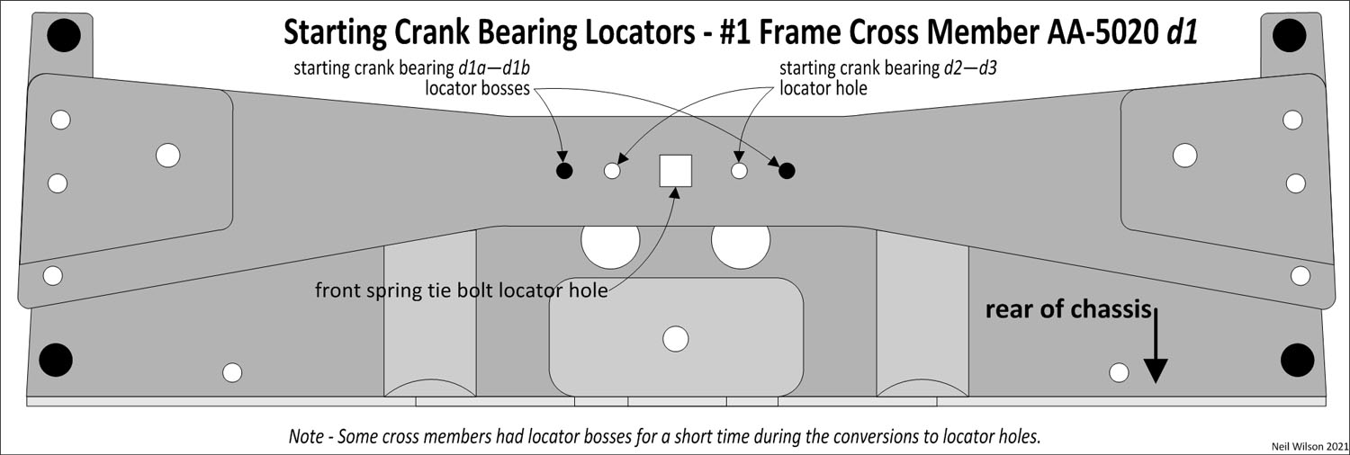
Note that the AA-Frame front cross member was changed to provide locators for the starting crank bearing designs:
The d1a and d1b bearings were kept from shifting (left-to-right) by locators on the AA-frame front cross member – first by tabs and then by two domed bosses on either side of the bearing (the tabs may have only applied to the A-frame).
For the d2 and d3 bearings, two asymmetrical holes were punched to accept the 1/4″ radius bosses on the bottom of the bearings. The frame cross member continued with the two domed bosses on either side of the bearing for a short time during the conversion to holes.
Refer to the starting crank bearing locators shown in the drawing below.
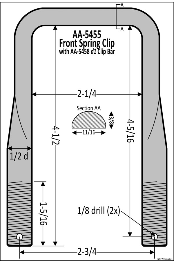
Front Spring Clips – AA-5455
Spring clips were forged steel. They were a square-style to fit the flat flanges of the A-5461 starting crank bearing. There was a half-round upper-section (across the top and down part of the sides). The lower-sections were 1/2″ round with 1/2-20 threads at the lower end of each leg.
The initial clip was AA-5455 as shown in the drawings below.
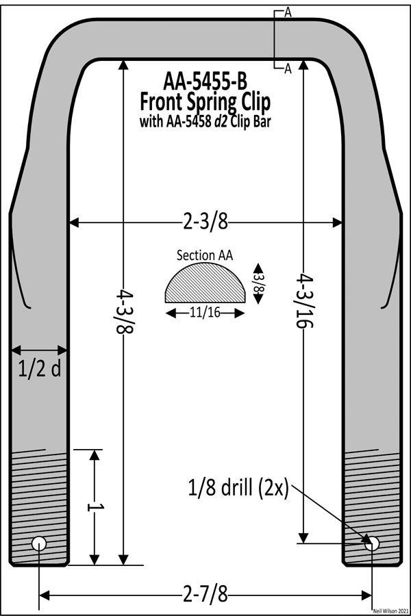
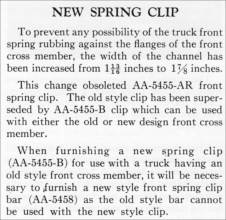
The AA-frame front cross member channel width was increased from 1-13/16″—1-7/8″ as per the January 1929 Ford Service Bulletin (see the snapshot of this information below). This change likely occurred in August 1928 with the introduction of the AA-5020 d2 front cross member.
Note that the AA-5455 clip and AA-5458 d1a—d1b clip bars could not be used with this redesigned AA-frame front cross member.
The front spring clip was changed with this channel width increase. The prior clip became AA-5455-AR for service and the new production clip was AA-5455-B.
The new AA-5455-B clip had a 1/8″ wider inside dimension. It was 1/8″ shorter and threads were 1″ high as compared to 1-5/16″ thread high for the AA-5455-AR clip. Refer to the drawings below.
The AA-5455-B clips could only be used with a new style front spring clip bar. Refer to AA-5458 d2.
Both clip designs were a black gloss finish. The nuts and cotters were unfinished. This was before assembly-line-spraying.
Installation hardware was (four of each):
- A-21839 nut – 1/2-20 (9/16 x 3/4) castle
- A-23531 cotter – 3/32 x 3/4
Front Spring Clip Bar – AA-5458
The clip bar was a steel forging with a gloss black finish before assembly-line-spraying. There were two clip bar designs.
The d2 design was a result of the frame front cross member channel width increase as explained in the section above (Front Spring Clip – AA-5455).
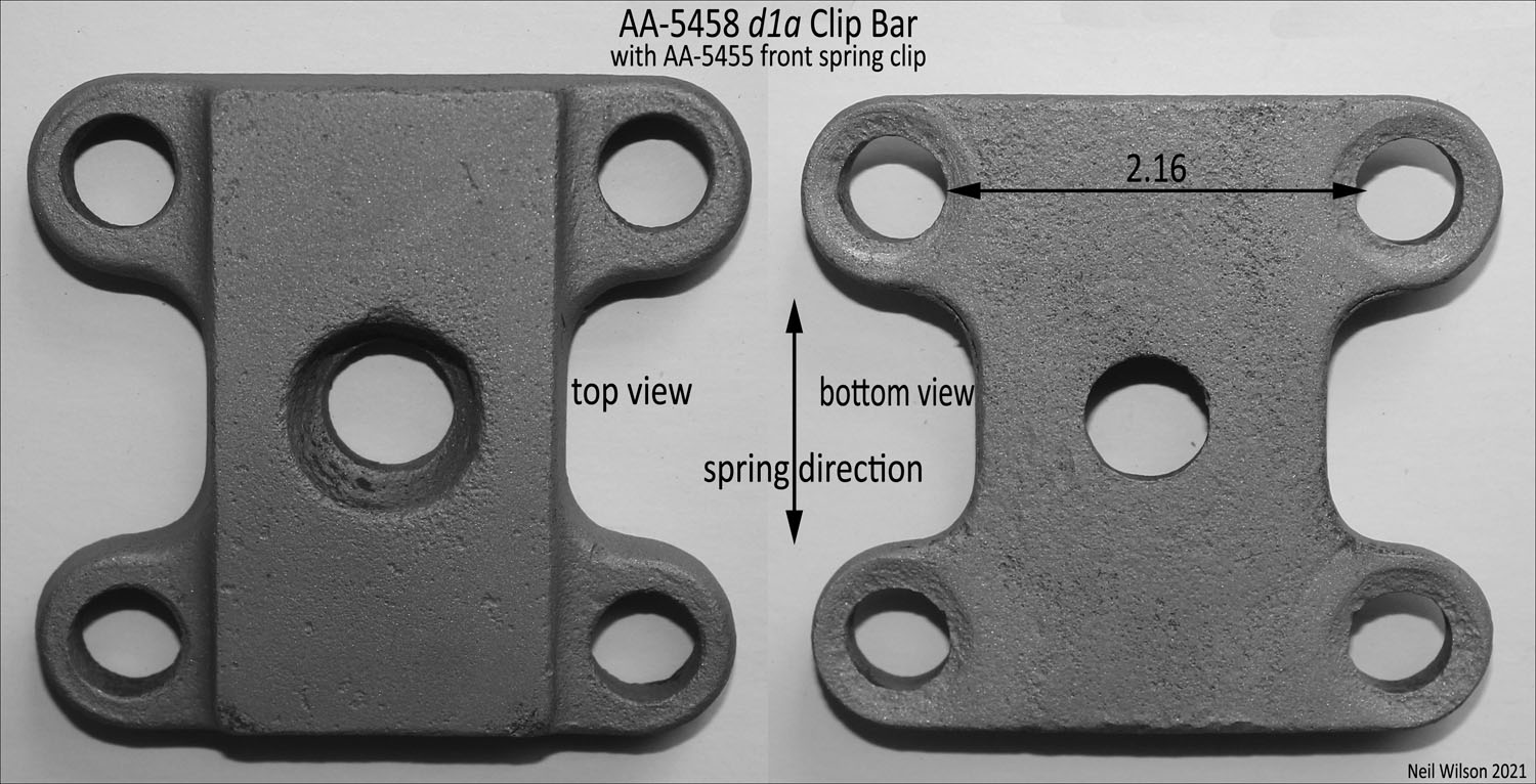
Clip Bar AA-5458 d1a-d1b
These two clip bar designs were used with AA-5455 front spring clips. The design change date between d1a and d1b is unknown.
Note – Without the Ford drawing to review, the A-chassis clip bar A-5458 seems to be the same dimensions as the d1a/b clip bars. The A-chassis clip bar was changed to have a bevel at each clip hole as per the 9/29 Ford service bulletin. That design change easily identifies it as the A-chassis clip bar.
d1a – Shown below, the bottom of this clip bar was flat and had a center hole. The top had a larger opening for clearance of the spring center bolt-nut.
d1b – The bottom of this clip bar was also flat but without a center hole. The top had a recess for clearance of the spring center bolt-nut. This design has been found on an early February 1928 AA truck.
Clip Bar AA-5458 d2
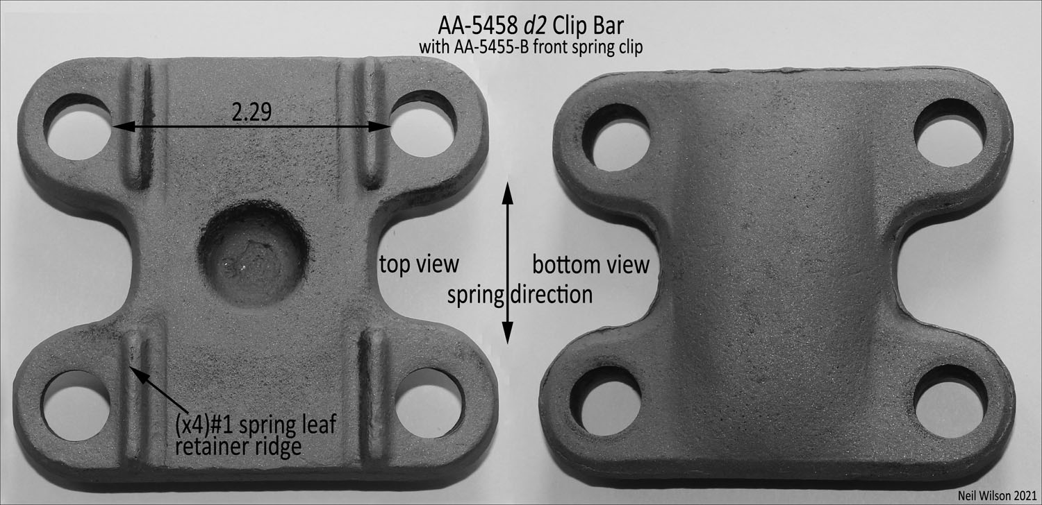
This clip bar design is shown above. It was used with AA-5455-B front spring clips. This d2 clip bar was wider than the prior d1a/b clip bars.
It had raised spring leaf retainer ridges (two on front and two on rear). Spring leaf #1 rested between these retainer ridges.
Front Spring Hangers/Bars – A-5465/A-5468
The A-chassis front spring hangers (aka shackles) and hanger-bars were used with the AA-5310 front spring assembly.
There were two designs of spring hangers:
d1 – with single or double Ford script and offset cotter holes – used into March 1928.
d2 – no Ford script and offset cotter holes – used 3/28—12/29. Hardware was as follows:
- A-21794 nut – 7/16-20 (29/64 x 11/16) castle
- A-23531 cotter – 3/32 x 3/4
- A-24404 lubricator fitting – 5/16 drive type
There were three designs of spring hanger-bars:
d1 – 2-3/8 long x 31/31 wide x 1/4 thick (45° clipped corners) and stamped Ford script (with or without a T7648 stamping) – 12/27.
d2 – elongated figure “8” shape (aka dog-bone shape) – with stamped Ford script through 3/28; without script – 4/28—3/29.
d3 – same as d1 but without any stampings – 4/29—12/29.
Before assembly-line-spraying, hangers and bars were a semi-gloss black lacquer finish. Nuts, cotters, and lubricator fittings were unfinished. Per the RGJS, the lubricator fittings could have been cadmium plated.
Note – more details and photos for these A-chassis parts are found on page 23-10 of the RGJS.
Restoration Thoughts
Refer to “Model A Ford Mechanics Handbook Vol. I” for details on front spring removal, disassembly, arching, assembly, and installation. This information is for the A-chassis 10-leaf front spring. But the information applies to the AA-chassis front spring as well. The following are highlights:
- The AA-5310 drawing above indicates that a .015 feeler must go under the ends of leaves 1/8—3/8 inches. Grinding leaves may be required to insure this gap. Grinding of the tops of leaves may be required to eliminate ridges made by leaves above from years of use.
- Restored leaves should be painted with a rust oxidizer (Extend is recommended in the Handbook).
- The Handbook recommends a Slip-Plate coating between leaves. The following Ford specification is provided in the AA-5310 drawing above – “When assembling spring, leaves having surface in contact must be coated with thick paste of graphite ground in oil”
- After assembly of the front spring (as shown in the AA-5310 drawing above), it should be painted. The Handbook recommends black Rustoleum.
- The Handbook recommends gluing an 8″ strip of body welt (anti-squeak) to the top of the spring stack (leaving a hole for the square center bolt-head). The top of the anti-squeak should be coated with grease.
Page Contents