
2024/01/11 update
Page Contents
AA Frame Overview
There were eight basic frame assemblies in the Ford Parts Price List booklets (i.e. as purchased through service). These are listed below.
There were also Ford internal frame assemblies for different builds depending on the truck being assembled.
|
Note – On the assembly lines, each frame was build with appropriate parts based on internal company instructions for a given order. Consequently, an order for an open cab platform truck with short running boards and another order for a panel delivery truck had different frame assemblies built.
The 5/11/28 engineering drawing for the AA frame assembly lists ids AA-5003, AA-5004, and AA-5005 and contains instructions for different builds. As an example, for a build with an open cab, the location for the rear body bolt holes were shown with the instructions of “1/2 drill in place 2 holes for open cab”.
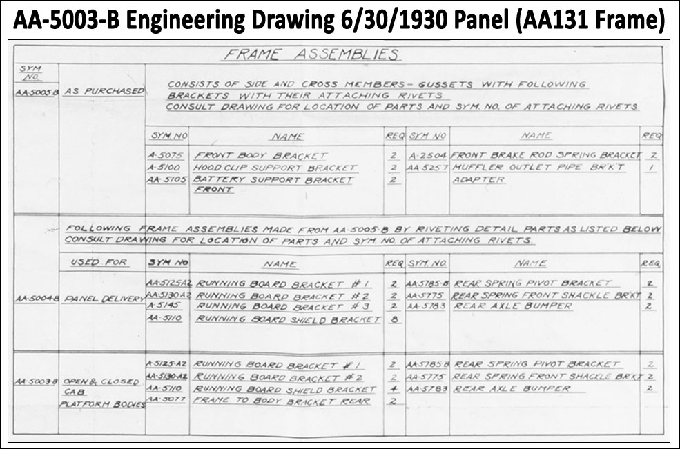
The instructions above show the makeup of the frame sold through service as AA-5005-B (i.e. “As Purchased”), the AA-5004-B frame makeup for AA’s with a panel delivery body, and the AA-5003-B frame makeup for a cab-only build or cab-platform build.
Note that the frame makeup for the express truck is not shown. This frame would have been the AA-5004-B frame makeup plus the AA-5077 frame to body bracket.
1928—1929 AA131 Frame Assembly AA-5005 d1 & d2
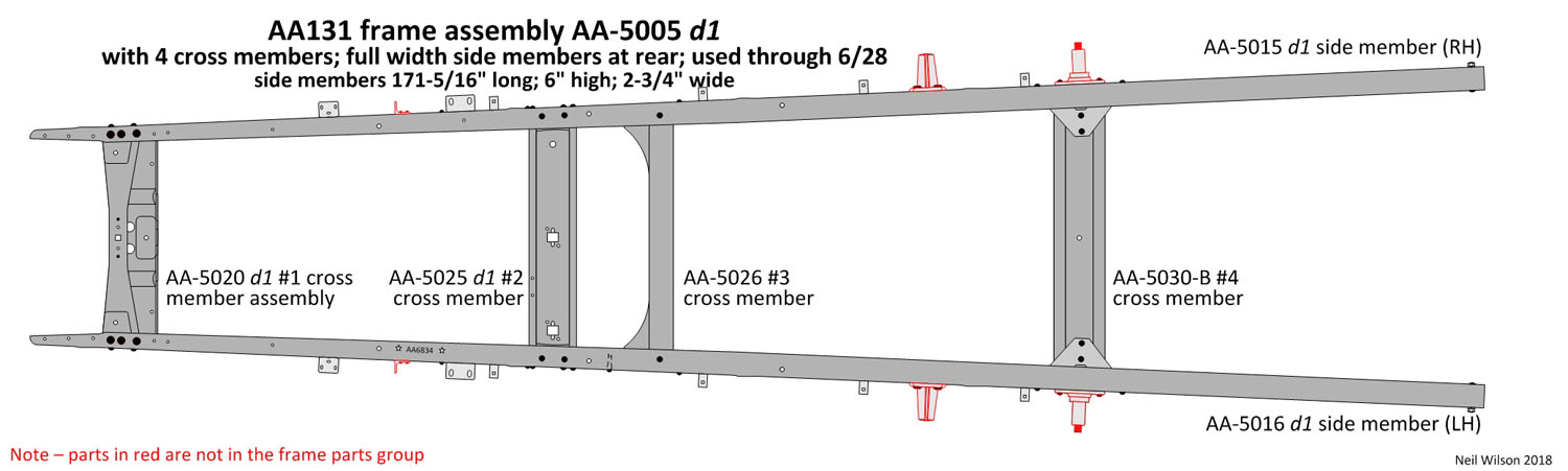
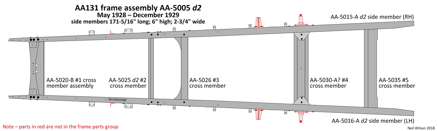
All 1928 and 1929 AA’s had a 131-1/2″ wheel base and used the AA-5005 frame assembly. There was a four, cross member d1 frame assembly and a five, cross member d2 frame assembly.
However, within these designs there were many frame assembly changes. By late 1929 all of the frame assembly parts had been modified from their December 1927 design.
Frame Assembly AA-5005 d1 & d2 Drawings Gallery
A brake down of the many assembly parts with information identifying the numerous changes made through December 1929 follows.
Note – It was not uncommon for owners to install the 1930/1931 rear axle in their 1928/1929 AA’s. This was not a Ford factory set-up. Today’s AA’ers are sometimes confused in identifying the year of their trucks because of a rear axle conversion.
When this conversion occurred, the frame #1 and #4 cross members are keys to identifying the correct year of the AA.
The February 1930 Ford Service Bulletin provided instructions for making this rear axle conversion. After a conversion, the AA had 1930/1931 rear wheels but continued using 1928/1929 front wheels.
Links – 1928/1929 AA131 Frame AA-5005 d1 & d2 Side & Cross Members
Side Members 1928-1929
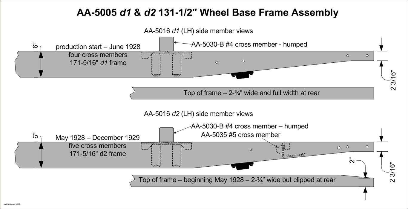
Frame assembly AA-5005 d1 used design 1 side members AA-5015/16 (RH & LH). The top and bottom flanges were the full width of 2-3/4″ all the way to the rear. Frame assembly AA-5005 d2 used design 2 side members AA-5015/16 (RH & LH). The top and bottom flanges were clipped at the rear leaving a flange width of 2″ at the rear.
These two side member designs are shown in the drawing above.
Both of these side members were modified many times during their production time period to accommodate changes to frame assembly components.
Cross Member #1 1928-1929
The #1 cross member was designed for a spring with 1-3/4″ wide leaves. This spring was used for all 1928/1929 AA’s.
The various #1 cross members were as shown in the drawing gallery and described below.


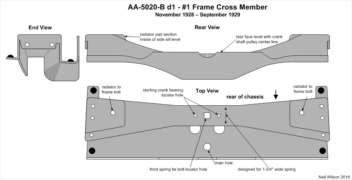

AA-5020 d1 – Production start through August 1928 – The initial design had a solid front engine support on the rear face. There was a flat trough, a 1/2” drain hole, and a strengthening rib on each side of the trough. This was basically a heavier design of the second A chassis #1 cross member.
AA-5020 d2 – Starting August 1928 – The ribs in the trough were eliminated and the trough was changed to formed a radius at the drain hole rather than having a flat area. This #1 cross member also had the solid front engine support on the rear face.
AA-5020-B d1 – Starting November 1928 – The solid engine support extensions on the rear face were cut off straight to the pulley’s center line and the trough was redesigned for the three- point A chassis engine support with a flat area and larger drain hole.
AA-5020-B d2 – Starting Late 1929 – The rear face was changed to curve under crank shaft and the radiator support areas were raised to be the same height as the top of side members.
Cross Member #2 1928-1932
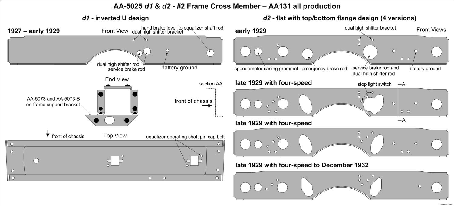
AA-5025 d1 – 1927 through early 1929 – This #2 cross member was an inverted “U” shape and designed for the equalizer type brake cross shaft. It was modified in late 1928 to include holes for emergency brake rod parts for those AA’s assembled with emergency brakes.
AA-5025 d2 – Early 1929 through production end – This #2 cross member had a flat face with top and bottom flanges. The punched holes in the face changed four times. The fourth version was used starting late 1929 to the production end (1932).
Cross Member #3 1928-1929 (+ early 1930)
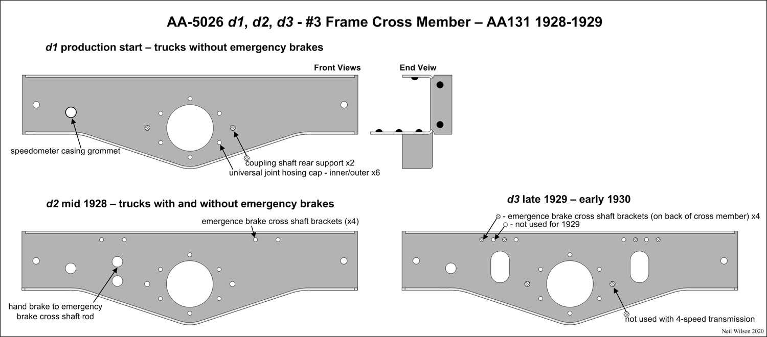
AA-5026 d1 – 1927 through mid-1928 – This design was for trucks without emergency brakes. There was no provision for installing the emergency brake cross shaft or a hole for a center hand brake lever to cross shaft rod.
AA-5026 d2 – Starting Mid 1928 – Additional holes were added for emergency brake cross shaft installation on the upper-rear face.
A hole was added for the center hand brake lever to cross shaft rod. Note that most 1928 AA’s continued to be assembled without emergency brakes through 1928.
AA-5026 d3 – Starting Late 1929 – This was a 1929 to 1930 cross-over design. It was redesigned for the emergency brake cross shaft on either the rear side for 1929 AA’s or on the front side for 1930 AA’s.
Cross Member #4 1928-1929
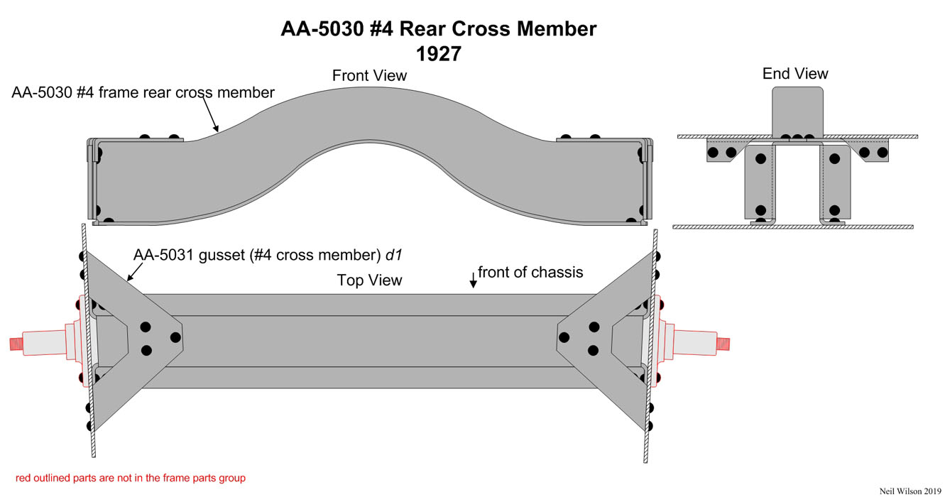
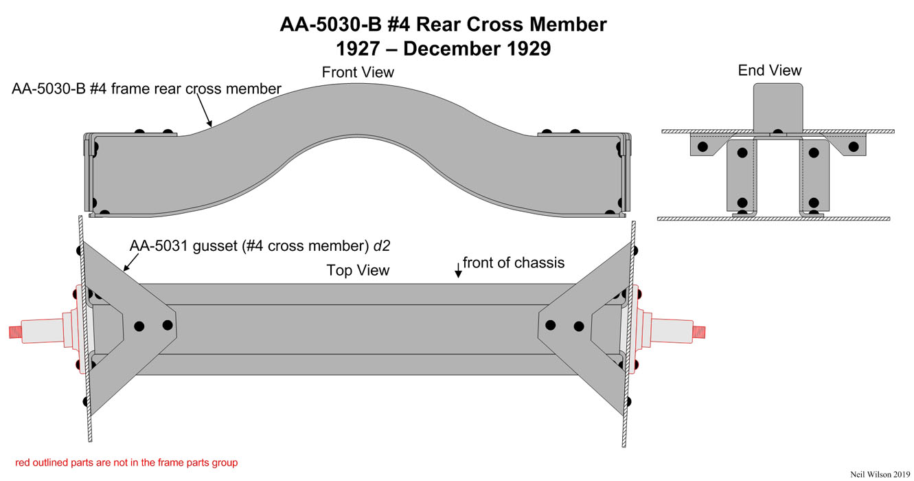
This cross member was designed with a hump in the middle to allow for clearance of the worm drive rear axle drive shaft/torque tube.
For a short time in 1927, #4 cross member AA-5003 with AA-5031 d1 gusset was used in production.
A new AA-5030-B #4 cross member was then used through December 1929. AA-5031 d2 gusset was used.
The only difference between the assemblies was the number of rivets used for each gusset installation. AA-5030 used seven rivets and AA-5030-B used four rivets.
Cross Member #5 1928-1929
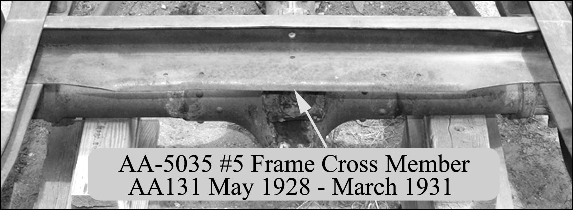
Beginning in May 1928, AA-5035 #5 cross member was added to the frame. This resulted in a redesigned platform wheel carrier which was attached to the cross member rather than to the platform body.
The four rivet holes for the carrier front hinges can be seen in the photograph above. The side member rear flanges were clipped at the same time.
These two changes were the initial differences between the AA-5005 d1 and d2 frames.
The AA-5035 #5 cross member was also used through March 1931 for the AA-5005 d2 and AA-5005-B d1 frame assemblies.
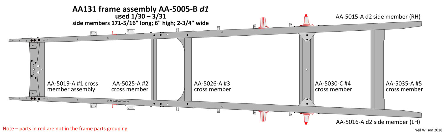
1930—1931 AA131 Frame Assembly AA-5005-B d1
The AA-5005-B d1 frame was the new assembly introduced for 1930 (see the drawing below). This frame assembly was used through March 1931 for the AA131 when it was replaced with assemblies AA-5005-B d2 and AA-5005-D.
The two changes for this assemble were new #1 and #4 cross members.
Cross member #1 was designed for 2-1/4″ wide front spring leaves (same width as the A chassis rear spring).
With the introduction of the new bevel gear rear axle, cross member #4 was redesigned to be flat across the top.
Links – 1930/1931 AA131 Frame AA-5005-B d1 Side & Cross Members
Links – 1930/1931 AA131 Frame AA-5005-B d1 Side & Cross Members
Side Members 1930-1931 (of AA-5005-B d1 frame assembly)
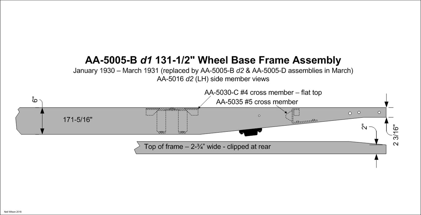
The AA-5015/16 d2 (RH & LH) side members were carried over from the 1929 frame assembly.
The side member flanges continued to be clipped at the rear as show in the drawing above.
Cross Member #1 1930-1931 (of AA-5005-B d1 frame assembly)
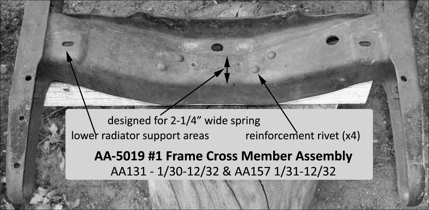
New AA-5019 #1 cross member assembly was designed for the 1930 AA-5005-B d1 frame assembly and was used for all AA131‘s to the end of production. Starting in January, a heavy duty front end assembly with a 2-1/4″ wide front spring was introduced. The #1 cross member assembly therefore had a wider throat to accommodate the new spring. A reinforcement was riveted to the inside of the throat making a much stronger assembly.
The cross member’s radiator support sections were lower than the underside of the side member flanges. This was in preparation for the AA radiator which was not released until June 1930 for use with the 76-B open cab, 82-B closed cab, and 85-B panel delivery. Until June 1930, the 76-A open cab, 82-A closed cab, and 85-A panel delivery were the production body types. The 1929 radiator design was used with additional pads to raise the radiator to clear the starting crank bearing.
Cross Member #2 1930-1931 (of AA-5005-B d1 frame assembly)
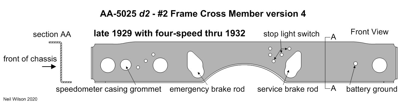
This was a carryover of the late 1929 AA-5025 d2 version 4 #2 cross member.
It was used to the end of production (December 1932).
Cross Member #3 1930-1931 (of AA-5005-B d1 frame assembly)
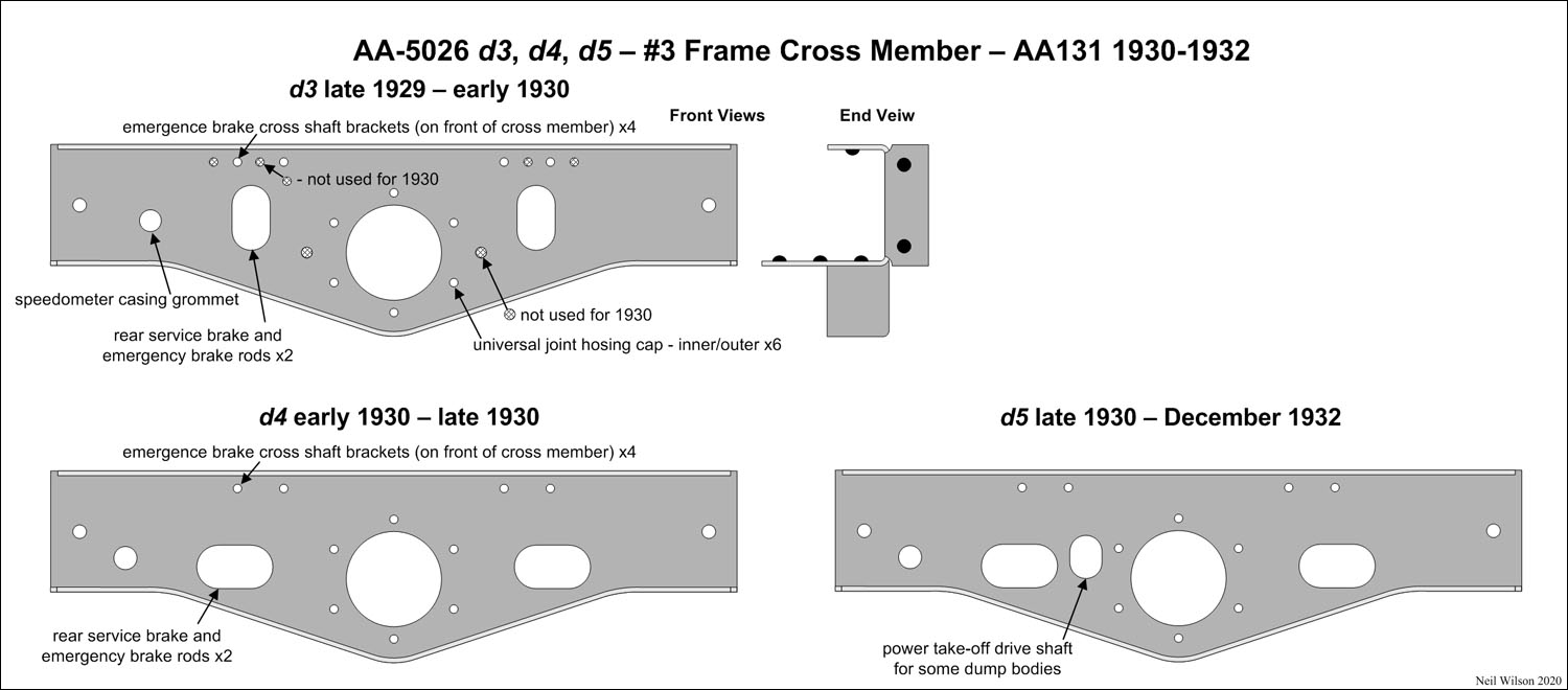
AA-5026 d4 – Used in early 1930 – late 1930 – Holes which were only used for the 1929 AA chassis were eliminated.
AA-5026 d3 – Used in early 1930 – This was a carryover of the late 1929 AA-5026 d4 version 4 cross member.
AA-5026 d4 – Used in early 1930 – late 1930 – Holes which were only used for the 1929 AA chassis.
AA-5026 d5 – Starting in late 1930 – An extra hole was punched in the cross member for the power take-off drive shaft of some dump bodies. This design was used through December 1932.
Cross Member #4 1930-1931 (of AA-5005-B d1 frame assembly)
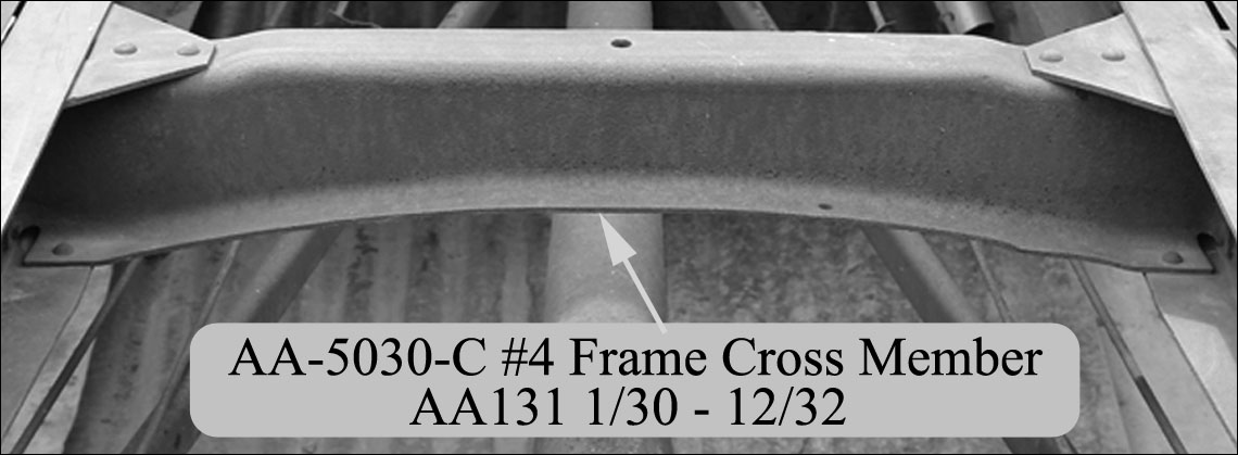
Starting in January 1930 a new bevel gear rear axle was put into production. This allowed the #4 cross member to be designed flat across the top as shown in the photograph.
This cross member was used through the end of production (12/32) for the AA131.
Cross Member #5 1930-1931 (of AA-5005-B d1 frame assembly)
The photograph above shows the AA-5035 #5 frame cross member used for the AA-5005-B d1 frame.
This cross member was a carryover from 1928-1929.
1931—1932 AA131 Frame AA-5005-B d2 and AA-5005-D Assemblies
Starting in March 1931, Ford replaced the AA131 frame assembly with two frame assemblies. Ford referenced these as the “long” and “short” assemblies.
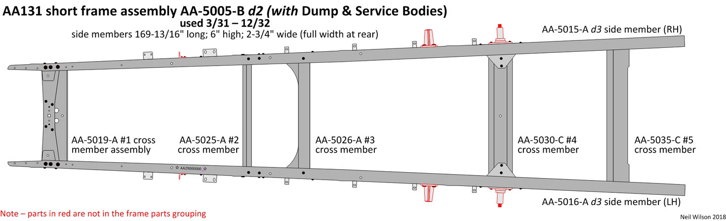
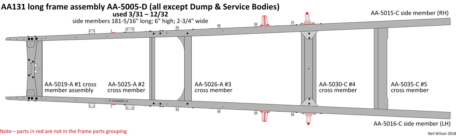
For all AA’s (except Dump & Service Body AA’s) the long AA-5005-D frame was used. Dump and Service Body AA’s used the short AA-5005-B d2 frame.
Links – 1931/1923 AA131 Frame AA-5005-B d2 & AA-5005-D Side & Cross Members
Side Members 1931-1932 (of AA-5005-B d2 and AA-5005-D frame assemblies)
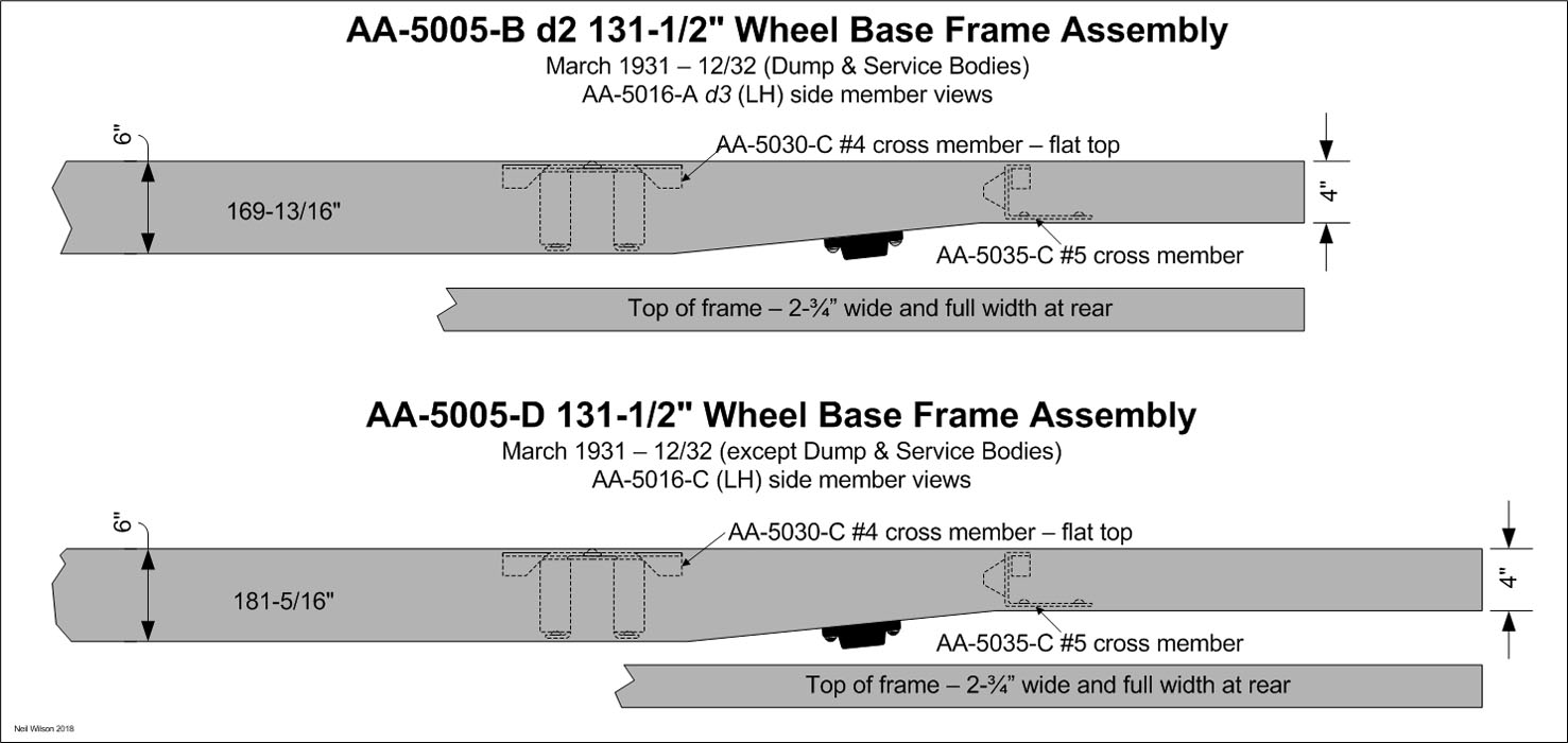
The AA-5005-B d2 frame assembly had 169-13/16″ long AA-5015/16-A d3 side members (1-1/2″ shorter than the prior frame). See the drawing above, upper image.
Note that the new short frame carried the same AA-5005-B part id as the prior frame.
The new design short frame was provided when the prior frame was ordered through service.
The AA-5005-D frame assembly had 181-5/16″ long AA-5015/16-C side members (10″ longer than the prior frame) as shown in the lower image of the drawing above.
Cross Member #1 1931-1932 (of AA-5005-B d2 and AA-5005-D frame assemblies)
This AA-5019 #1 cross member assembly was a carryover from the AA-5005-B d1 frame assembly.
It was used for the AA131‘s to the end of production. It was also used 1/31-12/32 for the AA157.
Cross Member #2 1931-1932 (of AA-5005-B d2 and AA-5005-D frame assemblies)
This was a carryover of the late 1929 AA-5025 d2 version 4 #2 cross member.
It was used to the end of production (December 1932).
Cross Member #3 1931-1932 (of AA-5005-B d2 and AA-5005-D frame assemblies)
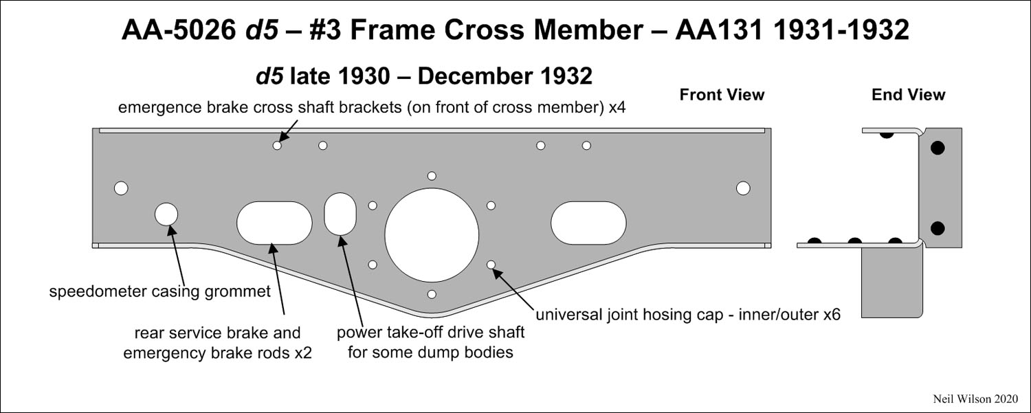
This was a carryover of the 1930-1931 AA-5026 d5 frame cross member.
It was used to the end of production (December 1932).
Cross Member #4 1931-1932 (of AA-5005-B d2 and AA-5005-D frame assemblies)
This AA-5030-C, #4 cross member, was a 1930 carryover.
It was used through the end of production for the AA131 (December 1932).
Cross Member #5 1931-1932 (of AA-5005-B d2 and AA-5005-D frame assemblies)
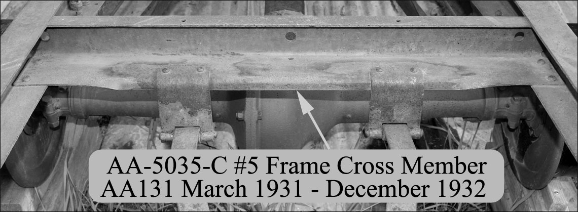
AA-5035-C #5 frame cross member’s front face and bottom flange formed a 90° angle unlike than the prior AA-5035 part. The prior part was obsoleted and this new AA-5035-C part was supplied through service.
The April 1931 Service Bulletin provided installation instruction requiring this cross member to be slightly bent to conform to the prior frame’s longer taper.
1930—1932 AA157 Frame AA-5006/08 Assemblies
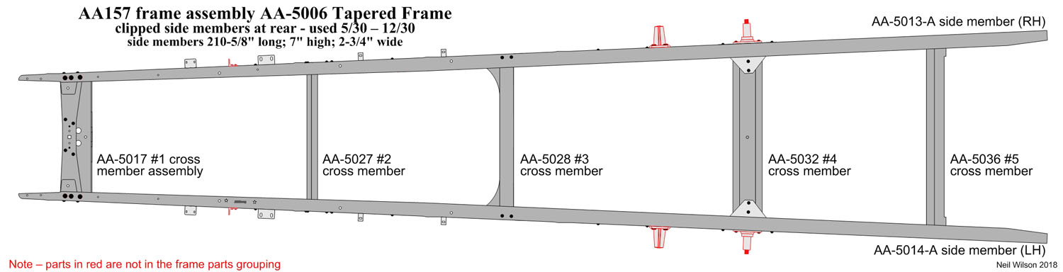
The long wheel base AA chassis was released as a chassis only in May of 1930. In June 1930 the 82-B closed cab was first produced. In July the AA157 was also offered with the 185-A platform (plain platform or with 186-A stake racks). Frame assembly AA-5006 was used through December of that year. It was a tapered design and a longer version of the AA131 frame.
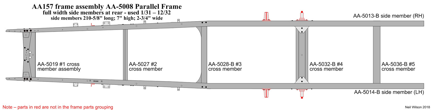
Starting in January of 1931 a redesigned AA-5008 frame as put into production. The rear section of the side members were parallel starting about 1″ behind the #3 cross member.
These two frames are shown in the gallery below.
Links – 1930/1932 AA157 Frame AA-5006 & AA-5008 Side & Cross Members
Side Members AA157 (of AA-5006/08 frame assemblies)
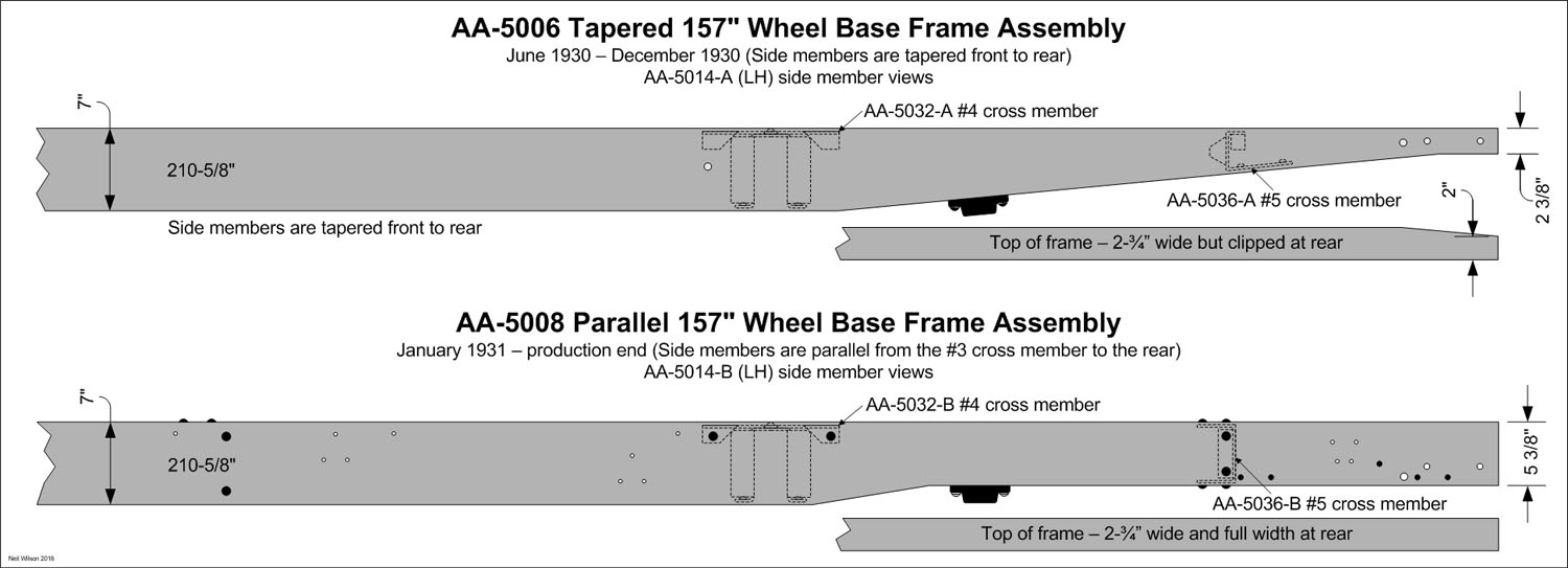
Frame side members AA-5013/14-A (RH & LH) were used for the tapered, AA-5006 frame assembly. These side members were 7″ high as compared to the 6″ high AA131 side members. The side member’s bottom edge had a long upwards slope from the #4 cross member similar to the AA131 frame side members used during the same time period.
Beginning in January 1931 the new parallel, AA-5008 frame assembly used new AA-5013/14-B (RH & LH) side members. These side members had a short upwards slope from the #4 cross member resulting in a stronger design. Also, the flanges of the side members were not clipped at the rear like the AA-5006 tapered frame side members.
Cross Member #1 AA157 1930-1932 (of AA-5006/08 frame)
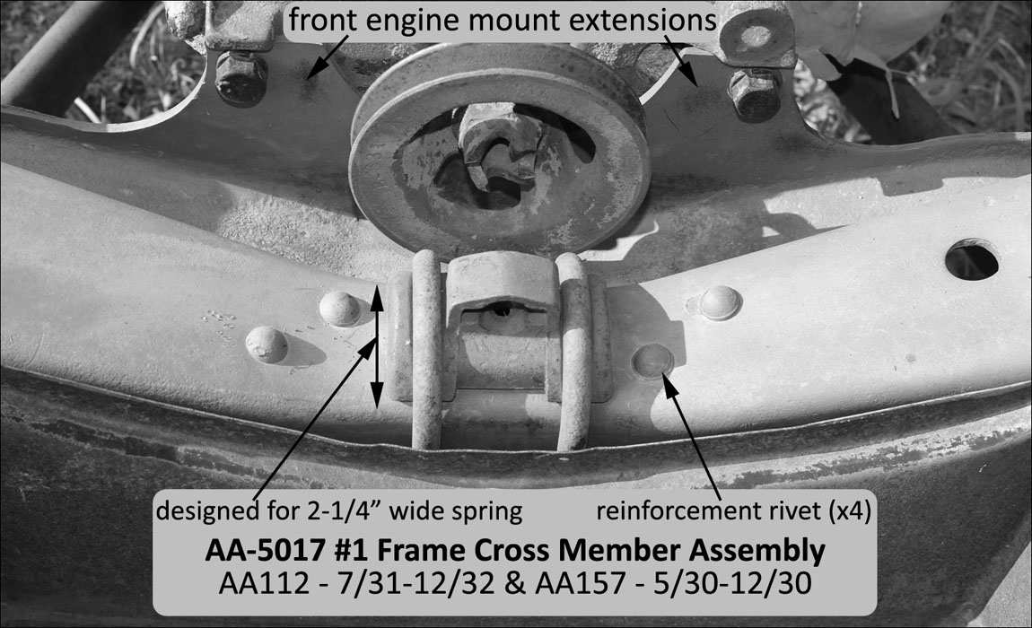
The AA-5017 #1 Frame Cross Member Assembly with extensions for the front engine mount is shown above. This cross member was used for both the AA157 tapered frame and the AA112 frame.
It was similar to the 1928 cross members with engine mount extensions.
The AA-5019 #1 Frame Cross Member Assembly is shown above. This cross member was used for both the AA157 parallel frame starting 1/31and the AA131 frame starting 1/30.
Both the AA-5017 and AA-5019 #1 cross members were an assembly with a reinforcement riveted to the underside of the cross-member throat.
Cross Member #2 AA157 1930-1932 (of AA-5006/08 frame)
This cross member was part AA-5027. It had a flat face with top and bottom flanges (basically the same design as the AA-5025 d2 (version 4) cross member used for the AA131 starting in late 1929.
It was used to install a speedometer cable grommet, stop light switch, battery ground, and battery support. It included holes for the passage of service and emergency brake rods.
Cross Member #3 AA157 1930-1932 (of AA-5006/08 frame)
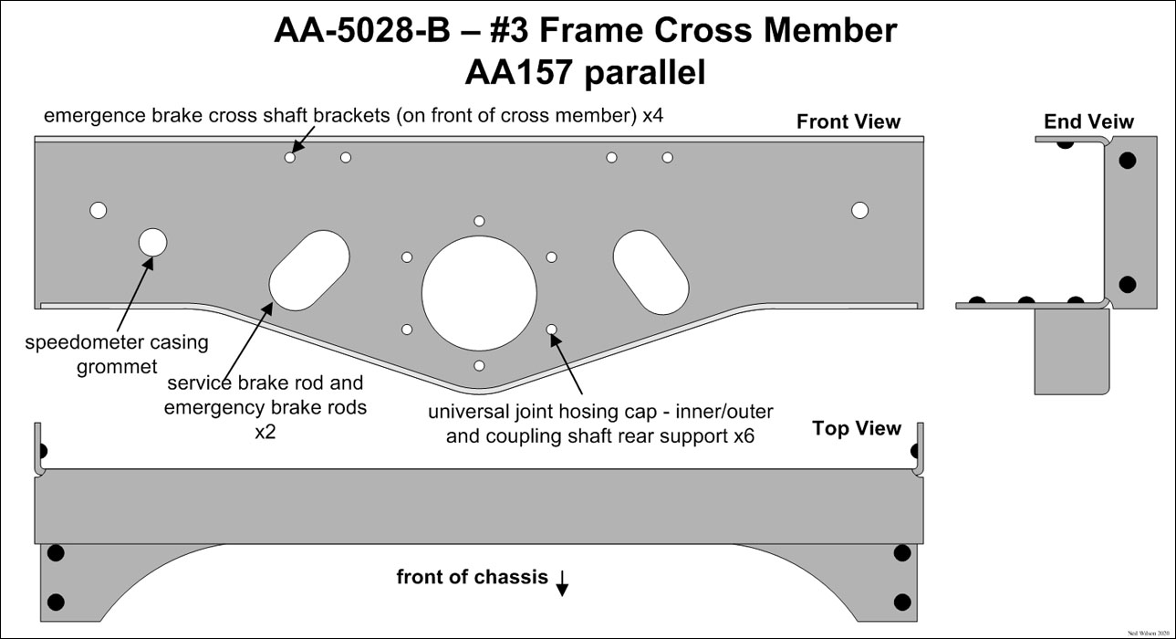
Cross member #3 was part AA-5028-A for the 1930 157″ tapered frame and AA-5028-B was for the 1931 157″ parallel frame. The drawing shows AA-5028-B.
These cross members were designed to fit the 7” tall side members and place the rear axle torque tube at the same angle as the AA131 chassis.
Cross Member #4 AA157 1930-1932 (of AA-5006/08 frame)
Cross member #4 was part AA-5032-A for the 1930 157” tapered frame. The 157” parallel frame used part AA-5032-B.
These cross members were an inverted “U” with a flat top and bottom flanges. Except for the width, these cross members were the same design as the corresponding AA-5030-C cross member used for the AA131.
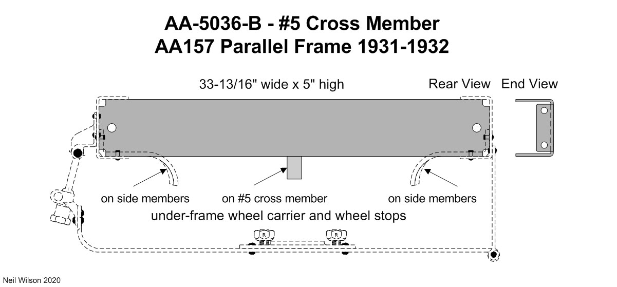
Cross Member #5 AA157 1930-1932 (of AA-5006/08 frame)
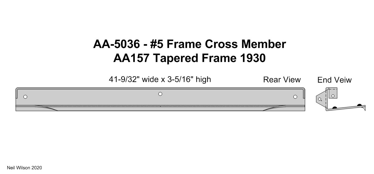
For the AA-5006 tapered frame, the #5 cross member was a wider version of the AA131 #5 cross member. The open side faced the rear. Most of the lower flange was curved downward.
Under-body wheel carrier front hinges attached to this cross member for AA’s with the 185-A platform body.
For the AA-5008 parallel frame, the #5 cross member was a “C” design with the open side facing the front. The center under-frame wheel carrier wheel stop was riveted to the bottom of this cross member.
The gallery above has drawings of these two cross members.
1931—1932 AA112 Frame AA-5009 Assembly
There were 863 112″ drop center chassis to roll off the assembly line from July 1931 through December 1932. It was the last of the three AA chassis to be put into production. There were 445 of these chassis produced as complete trucks with the 315-A Standrive body type installed. Like the chassis shown below, the remaining 418 units were sold to independent body suppliers for installation of their body.
Information for the AA112 is sparse. The August 7, 1931 AA-5009 frame engineering drawing is extremely hard to see. This drawing provided the frame part id makeup.
The drop center chassis photograph below is dated 6/25/31. It may have been a per-production unit. The spare wheel was installed on the right for standard production.
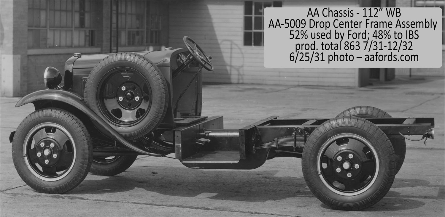
The AA-5009 frame had parallel side members starting at the rear of the drop frame section. The frame cross members would have been similar in design to the corresponding cross members of other frames. The length and height of the AA112 cross members would have been determined by the side members.
There were three cross members which consisted of #1 front, #2 center (at the spring pivot), and #3 rear. The frame channel assembly served as another cross member.
The drop frame section of the AA-5009 frame assembly can be seen in the photo above. This section was filled with the Frame Channel assembly AA-5066. This channel assembly was made up of AA-2067 channel and AA-5068 tunnel.
It is my guess that there was no coupling shaft. Therefore, the rear axle drive shaft and torque tube connected directly to the four-speed transmission with a universal joint.
AA112 Parts List
AA-5056 and AA-5050 RH frame side member assembly
AA-5057 and AA-5051 LH frame side member assembly
AA-5059 LH and AA-5060 RH – frame reinforcement
AA-5064 frame cross member #2 at spring pivot (like AA157 #3)
AA-5066 frame channel assembly (5067 channel and AA-5068 tunnel)
AA-5071 frame cross member #3 rear (like AA157 #5)
AA-5775-B rear spring front shackle bracket (also AA157 parallel)
AA-5785-C rear spring pivot bracket (also AA157 parallel)
Under construction below
Links – 1931/1932 AA112 Frame AA-5009 Side & Cross Members