
2023/12/01 update
Page Contents
Description – AA-4802 Coupling Shaft Assembly – AA’s with 3-speed
Links – Coupling shaft for AA’s with 3-speed transmission
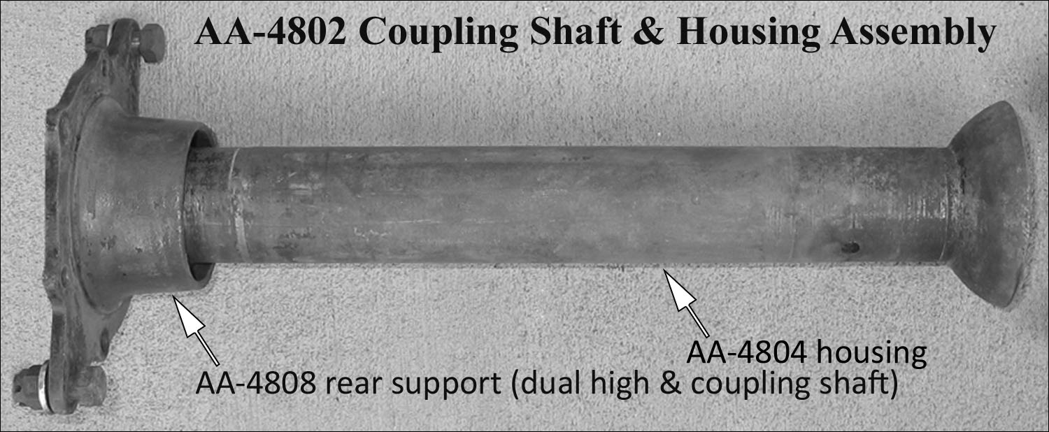
This AA-4802 assembly was used for AA131‘s with the A-chassis 3-speed transmission. It was used from the beginning of production until the introduction of the 4-speed transmission in September 1929.
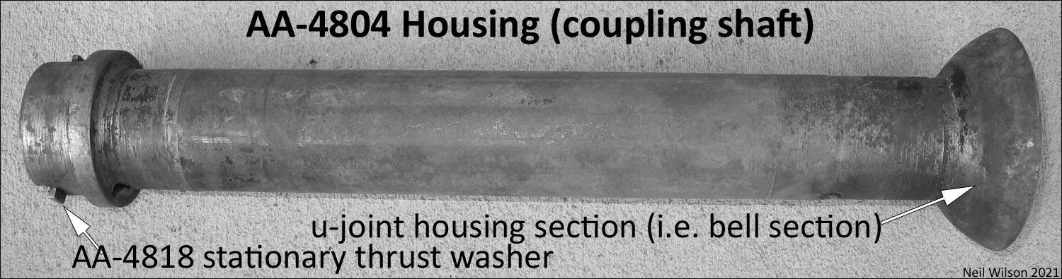
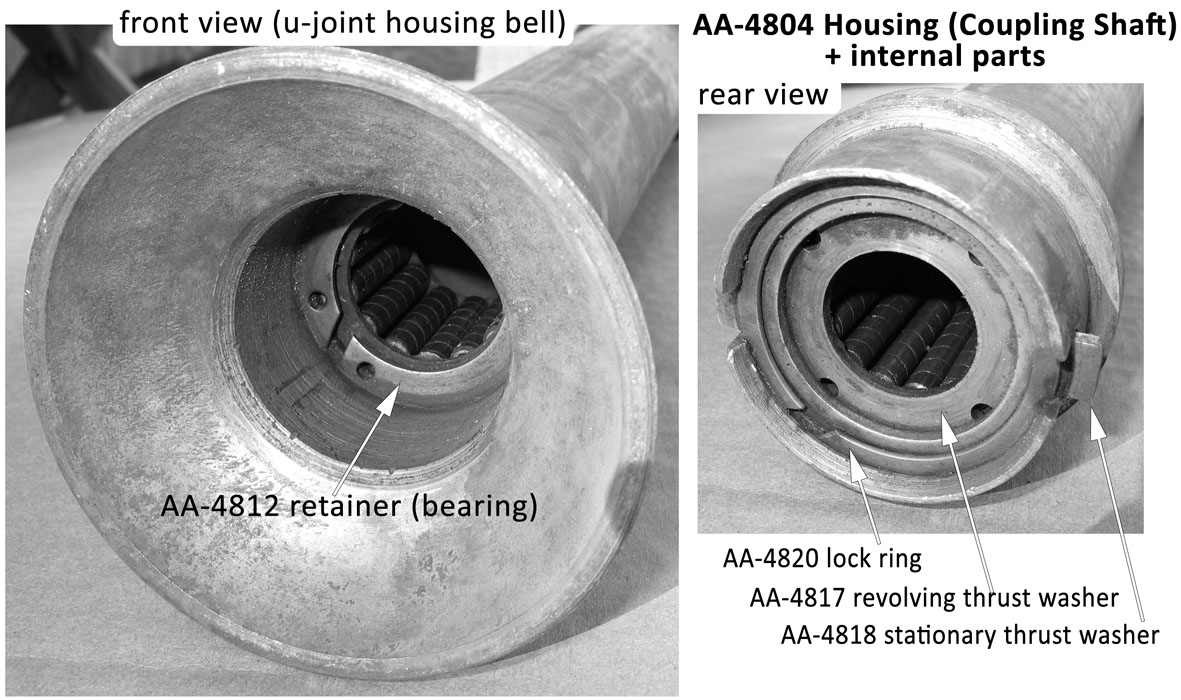
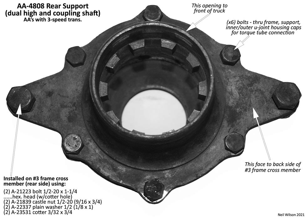
This assembly was, basically, designed as a short version of an A or AA drive shaft and torque tube. The front integral section of the coupling shaft housing was a bell-shaped, u-joint housing. To prevent the housing from revolving, the two tabs on a stationary thrust washer meshed with the internal teeth in the rear support bolted to the #3 frame cross member.
There were front and rear roller bearings to support the coupling shaft. These were the same as the AA-chassis drive shaft roller bearing.
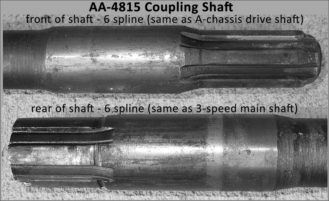
The shaft had six front splines which matched the A-chassis drive shaft splines. This allowed the A-chassis u-joint to be used at the front.
The six rear splines of the coupling shaft matched the 3-speed transmission main rear shaft splines. Consequently, the rear u-joint, front knuckle matched the 3-speed transmission u-joint, front knuckle.
Installation parts used for the coupling shaft at the 3-speed transmission were the same as the installation parts used for the A-chassis torque tube at the 3-speed transmission. The installation parts at the rear of the coupling shaft were unique to the AA-chassis until March/April of 1929. At that time, the A-chassis u-joint inner/outer caps were modified and became parts use by both the A and AA. See AA-4802 Installation.
The Ford, optional, dual high was an underdrive transmission which replaced the coupling shaft assembly.
Secondary transmissions, manufactured by independent suppliers, were used to replace this coupling shaft assembly. The 3-speed Warford transmission is one example. The AA-4808 dual high & coupling shaft rear support was used for this installation.
Note – Table part finish codes are found in “Part Description” column following the description. The code meanings are the same as used in the RGJS – (bst)-black satin; (bsg)-black semi-gloss; (bg)-black gloss; (c)-cadmium; (g)-Ford engine green; (r)-raven; (u)-unfinished; (z)-Zink
Gallery – AA-4802 Coupling Shaft Assembly (with 3-speed transmission)
Installations – AA-4802 Coupling Shaft Assembly – AA’s with 3-speed
AA131‘s came with the A-chassis 3-speed transmission through Aug/Sept 1929 when the 4-speed transmission was introduced.
Coupling shaft assembly AA-4802 was installed between the 3-speed transmission and the torque tube. Ford made a number of changes to the installation parts at those two locations. A major change occurred with the change from the d1 to d2 brake systems (see notes following).
Due to many changes in parts, installation versions have been established to define the installation of the AA-4802 coupling shaft assembly. These versions are – 3sV1-3sV4 (Installation @3-speed transmission) and ttV1-ttV2 (Installation @ torque tube).
Notes – AA brake system d1 and d2:
d1 brake system was for trucks without emergency brakes (applied to most 1928 AA’s). This system included an equalizer brake cross shaft design which was supported by sockets in the outer u-joint housing cap assembly.
d2 brake system was for trucks with emergency brakes starting in late 1928. This system used a solid brake cross shaft which eliminated any connection to the outer u-joint housing cap assembly.
Installations @ 3-speed transmission (AA-4802)
Installation Version 3sV1 – production start to mid/Dec 1927. Per Ford release records – used on the first “3400 cars”. These AA’s had the d1 brake system (i.e. without emergency brakes) – included left-hand brake lever, equalizer brake cross shaft, and equal bolt hole spacing for inner/outer u-joint housing caps.
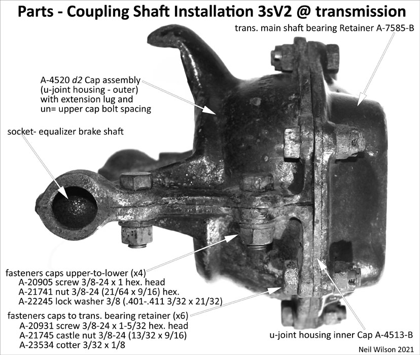
Installation Version 3sV2 – starting mid/Dec 1927 for AA’s with d1 brake system (i.e. without emergency brakes) – included left-hand brake lever, equalizer brake cross shaft, and un= bolt hole spacing for inner/outer u-joint housing caps.
Installation Version 3sV3 – used through Mar/Apr 1929 for AA’s with d2 brake system (i.e. with emergency brakes) – included center brake lever, solid brake cross shaft, and un= bolt hole spacing for inner/outer u-joint housing caps.
Installation Version 3sV4 – used starting Mar/Apr 1929 for AA’s with d2 brake system (i.e. with emergency brakes) – included center brake lever, solid brake cross shaft, and equal bolt hole spacing for inner/outer u-joint housing caps.
Installation 3sV1 through mid/Dec 1927
This 3sV1 installation version applied to the first 3,400 cars into mid/Dec 1927 approximately. It is not known if this applies to any AA-chassis since the first AA production date is unknown.
Any AA’s using this version had the d1 brake system (i.e. without emergency brakes) – included left-hand brake lever, equalizer brake cross shaft, and equal bolt hole spacing for inner/outer u-joint housing caps.
The 3-speed transmission main shaft bearing retainer, inner u-joint housing cap + gaskets, and outer u-joint housing cap assembly had equally spaced bolt holes.
The A-4520 d1 outer u-joint housing cap assembly had two interchangeable d1a and d1b styles. This assembly had extension arms with sockets for the equalizer brake shaft setup.
| Coupling Shaft Assembly (AA’s with 3-speed trans.) – installation V1 @ transmission | ||
|---|---|---|
| parts not covered by the coupling shaft parts group table | ||
| # | Part | Part Description (finish code) |
| Neil Wilson 2021 | ||
| VERSION 1 (V1) – to mid/Dec 1927 | ||
| …per Ford release records – used on the first “3400 cars” | ||
| …FYI – 1st AA prod. date unknown – consequently V1 may not apply to AA-chassis | ||
| 1 | ..A-7085 | Retainer (trans. main shaft bearing) 1/4″ bolt flange with = spaced bolt holes |
| 1 | ..A-24405 | Lubricator fitting (u-joint) check valve type (on middle-right side of A-7085) |
| 1 | ..A-7086 | Gasket (trans. main shaft bearing retainer) |
| fasteners – retainer to 3-speed trans. case | ||
| 4 | A-21116 screw 7/16-20 x 1 hex. head (u) | |
| 1 | ..A-7090 d1 | U-Joint assembly (rivet together – not repairable) |
| 1 | ..A-7095 | Retainer (u-Joint front knuckle) 1.18″ diam. approx. |
| fasteners – u-Joint to 3-speed trans. main shaft | ||
| 1 | A-20905 screw 3/8-24 x 1 hex. head (u) | |
| 1 | A-22245 lock washer 3/8 (.401-.411 3/32 x 21/32) (u) | |
| 1 | ..A-4513 | Cap (u-joint housing – inner) = spaced bolt holes |
| 2 | ..A-4515 | Gasket (u-joint housing inner cap) = spaced bolt holes |
| 2 | ..A-4516 | Felt (u-joint housing outer cap assy.) |
| 1 | ..A-4520 d1 | Cap assembly (u-joint housing – outer d1a and d1b) (bsg) = spaced bolt holes |
| with equalizer brake shaft sockets | ||
| d1a upper – special raised rib extension lug | ||
| d1a lower – “T” shaped raised area | ||
| d1b upper – extension lug | ||
| d1b lower – “D” shaped raised area | ||
| fasteners – cap assembly upper to lower | ||
| 4 | A-20905 screw 3/8-24 x 1 hex. head (u) | |
| 4 | A-21741 nut 3/8-24 (21/64 x 9/16) hex. (u) | |
| 4 | A-22245 lock washer 3/8 (.401-.411 3/32 x 21/32) (u) | |
| fasteners – caps to trans. bearing retainer | ||
| 6 | A-20931 screw 3/8-24 x 1-5/32 hex. head (u) | |
| 6 | A-21745 castle nut 3/8-24 (13/32 x 9/16) (u) | |
| 6 | A-23534 cotter 3/32 x 1/8 (u) | |
| AAAAAAAAA | aaaaaaaaaaaaaaaaaaaa aaaaaaaaaaaaaaaaaaaa aaaaaaaaaaaaaaaaaaaa aaaaaaa | |
Installation 3sV2 starting mid/Dec 1927 with d1 brake system
Starting mid/Dec 1927 this installation 3sV2 was used for AA’s with the d1 brake system (i.e. without emergency brakes) – included left-hand brake lever, and equalizer brake cross shaft.
The 3-speed transmission main shaft bearing retainer, inner u-joint housing cap + gaskets, and outer u-joint housing cap assembly had un= spaced bolt holes.
The A-4520 d2 outer u-joint housing cap assembly had extension arms with sockets for the equalizer brake shaft setup.
Most (possibly all) 1928 AA’s were produced without emergency brakes and therefore used this 3sV2 installation.
| Coupling Shaft Assembly (AA’s with 3-speed trans.) – installation V2 @ transmission | ||
|---|---|---|
| parts not covered by the coupling shaft parts group table | ||
| # | Part | Part Description (finish code) |
| Neil Wilson 2021 | ||
| VERSION 2 (V2) – starting mid/Dec 1927 for AA’s with d1 brake system | ||
| …brake system d1 was for AA’s without emergency brakes | ||
| …this included left-hand brake lever and equalizer brake cross shaft | ||
| 1 | ..A-7085-B | Retainer (trans. main shaft bearing) 1/4″ bolt flange with un= bolt hole spacing |
| 1 | ..A-24405 | Lubricator fitting (u-joint) check valve type (on bottom-right side of A-7085-B) |
| 1 | ..A-7086 | Gasket (trans. main shaft bearing retainer) |
| fasteners – retainer to 3-speed trans. case | ||
| 4 | A-21116 screw 7/16-20 x 1 hex. head (u) | |
| 1 | ..A-7090 d1 | U-Joint assembly (rivet together – not repairable) |
| 1 | ..A-7095 | Retainer (u-Joint front knuckle) 1.18″ diam. approx. |
| fasteners – u-Joint to 3-speed trans. main shaft | ||
| 1 | A-20905 screw 3/8-24 x 1 hex. head (u) | |
| 1 | A-22245 lock washer 3/8 (.401-.411 3/32 x 21/32) (u) | |
| 1 | ..A-4513-B | Cap (u-joint housing – inner) un= spaced bolt holes |
| 2 | ..A-4515-B | Gasket (u-joint housing inner cap) un= spaced bolt holes |
| 2 | ..A-4516 | Felt (u-joint housing outer cap assy.) |
| 1 | ..A-4520 d2 | Cap assembly (u-joint housing – outer) (bsg) un= spaced bolt holes |
| with equalizer brake shaft sockets | ||
| upper – un= spaced bolt holes and extension lug | ||
| lower – equal hole spacing and no raised area | ||
| fasteners – cap assembly upper to lower | ||
| 4 | A-20905 screw 3/8-24 x 1 hex. head (u) | |
| 4 | A-21741 nut 3/8-24 (21/64 x 9/16) hex. (u) | |
| 4 | A-22245 lock washer 3/8 (.401-.411 3/32 x 21/32) (u) | |
| fasteners – caps to trans.bearing retainer | ||
| 6 | A-20931 screw 3/8-24 x 1-5/32 hex. head (u) | |
| 6 | A-21745 castle nut 3/8-24 (13/32 x 9/16) (u) | |
| 6 | A-23534 cotter 3/32 x 1/8 (u) | |
| AAAAAAAAA | aaaaaaaaaaaaaaaaaaaa aaaaaaaaaaaaaaaaaaaa aaaaaaaaaaaaaaaaaaaa aaaaaaa | |
Installation 3sV3 through Mar/Apr 1929 with d2 brake system
This 3sV3 installation version was used through Mar/Apr 1929 for AA’s with a d2 brake system (i.e. with emergency brakes) – included center brake lever, solid brake cross shaft, and un= bolt hole spacing for inner/outer u-joint housing caps. Since most AA’s did not have separate emergency brakes through 1928, this 3sV3 installation version was basically used during the first three to four months of 1929.
The 3-speed transmission main shaft bearing retainer, inner u-joint housing cap + gaskets, and outer u-joint housing cap assembly had un= spaced bolt holes.
The A-4520-B outer u-joint housing cap assembly had an extension lug but did not have extension arms with sockets since there was a solid brake cross shaft.
| Coupling Shaft Assembly (AA’s with 3-speed trans.) – installation V3 @ transmission | ||
|---|---|---|
| parts not covered by the coupling shaft parts group table | ||
| # | Part | Part Description (finish code) |
| Neil Wilson 2021 | ||
| VERSION 3 (V3) – through Mar/Apr 1929 for AA’s with d2 brake system | ||
| …brake system d2 was for AA’s with emergency brakes | ||
| …this included break lever at shift tower and solid brake cross shaft | ||
| …un= bolt hole spacing for inner/outer u-joint housing caps | ||
| 1 | ..A-7085-C | Retainer (trans. main shaft bearing) 5/16″ bolt flange with un= bolt hole spacing |
| 1 | ..A-24405 | Lubricator fitting (u-joint) check valve type (on bottom-right side of A-7085-C) |
| 1 | ..A-7086 | Gasket (trans. main shaft bearing retainer) |
| fasteners – retainer to 3-speed trans. case | ||
| 4 | A-21116 screw 7/16-20 x 1 hex. head (u) | |
| 1 | ..A-7090 d1 | U-Joint assembly (rivet together – not repairable) |
| 1 | ..A-7095 | Retainer (u-Joint front knuckle) 1.18″ diam. approx. |
| fasteners – u-Joint to 3-speed trans. main shaft | ||
| 1 | A-20905 screw 3/8-24 x 1 hex. head (u) | |
| 1 | A-22245 lock washer 3/8 (.401-.411 3/32 x 21/32) (u) | |
| 1 | ..A-4513-B | Cap (u-joint housing – inner) un= spaced bolt holes |
| 2 | ..A-4515-B | Gasket (u-joint housing inner cap) un= spaced bolt holes |
| 2 | ..A-4516 | Felt (u-joint housing outer cap assy.) |
| 1 | ..A-4520-B | Cap assembly (u-joint housing – outer) (bsg) un= spaced bolt holes |
| AA’s with solid brake cross shaft | ||
| upper – un= spaced bolt holes and extension lug | ||
| lower – equal hole spacing and no raised area | ||
| fasteners – cap assembly upper to lower | ||
| 2 | A-20905 screw 3/8-24 x 1 hex. head (u) | |
| 2 | A-21741 nut 3/8-24 (21/64 x 9/16) hex. (u) | |
| 2 | A-22245 lock washer 3/8 (.401-.411 3/32 x 21/32) (u) | |
| fasteners – caps to trans. bearing retainer | ||
| 6 | A-20953 screw 3/8-24 x 1-7/32 hex. head (u) | |
| 6 | A-21745 castle nut 3/8-24 (13/32 x 9/16) (u) | |
| 6 | A-23534 cotter 3/32 x 1/8 (u) | |
| AAAAAAAAA | aaaaaaaaaaaaaaaaaaaa aaaaaaaaaaaaaaaaaaaa aaaaaaaaaaaaaaaaaaaa aaaaaaa | |
Installation 3sV4 starting Mar/Apr 1929 with d2 brake system
From production start, the inner/outer u-joint housing caps and gaskets use @ the torque tube for the AA-chassis were AA designated parts. Bolt holes were equally spaces.
Beginning Mar/Apr 1929, these parts were designated as A-chassis parts (i.e. part ids were changed).
These parts were used @ the 3-speed for both the A-chassis and AA-chassis. And, these parts became the Ford listed-parts for the AA @ the torque tube.
Actual physical changes were the addition of two 3/8” holes added to the inner cap for lubrication.
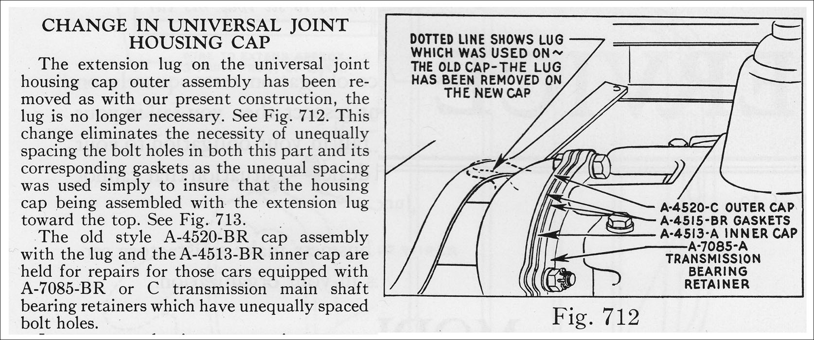
Also, casting embossment on the outer cap was changed from AA-4520 to A-4520-C.
The 3-speed trans. main shaft bearing retainer was redesigned and became A-7085-A. It had equally spaced holes for connection to the inner and outer caps and gasket.
This conversion was noted in the June 1929 Ford Service Bulletin.
AA’s continued to be produced with the A-chassis 3-speed transmission until the introduction of the 4-speed trans. in Aug/Sept 1929.
Installation 3sV4 was for AA’s with the d2 brake system (i.e. with emergency brakes) – included center brake lever and solid brake cross shaft.
| Coupling Shaft Assembly (AA’s with 3-speed trans.) – installation V4 @ transmission | ||
|---|---|---|
| parts not covered by the coupling shaft parts group table | ||
| # | Part | Part Description (finish code) |
| Neil Wilson 2021 | ||
| VERSION 4 (V4) – starting Mar/Apr 1929 for AA’s with d2 brake system | ||
| …this included break lever at shift tower and solid brake cross shaft | ||
| …equal bolt hole spacing for inner/outer u-joint housing caps | ||
| 1 | ..A-7085-A | Retainer (trans. main shaft bearing) 5/16″ bolt flange with equal bolt hole spacing |
| 1 | ..A-24405 | Lubricator fitting (u-joint) check valve type (on bottom-right side of A-7085-A) |
| 1 | ..A-7086 | Gasket (trans. main shaft bearing retainer) |
| fasteners – retainer to 3-speed trans. case | ||
| 4 | A-21116 screw 7/16-20 x 1 hex. head (u) | |
| 1 | ..A-7090 d1 | U-Joint assembly (rivet together – not repairable) |
| 1 | ..A-7095 | Retainer (u-Joint front knuckle) 1.18″ diam. approx. |
| fasteners – u-Joint to 3-speed trans. main shaft | ||
| 1 | A-20905 screw 3/8-24 x 1 hex. head (u) | |
| 1 | A-22245 lock washer 3/8 (.401-.411 3/32 x 21/32) (u) | |
| 1 | ..A-4513-A | Cap (u-joint housing – inner) equal spaced bolt holes |
| 2 | ..A-4515-A | Gasket (u-joint housing inner cap) equal spaced bolt holes |
| 2 | ..A-4516 | Felt (u-joint housing outer cap assy.) |
| 1 | ..A-4520-C | Cap assembly (u-joint housing – outer) (bsg) equal spaced bolt holes |
| AA’s with solid brake cross shaft; no extension lug | ||
| upper and lower equal spaced bolt holes and no safety lug | ||
| fasteners – cap assembly upper to lower | ||
| 2 | A-20905 screw 3/8-24 x 1 hex. head (u) | |
| 2 | A-21741 nut 3/8-24 (21/64 x 9/16) hex. (u) | |
| 2 | A-22245 lock washer 3/8 (.401-.411 3/32 x 21/32) (u) | |
| fasteners – caps to trans. bearing retainer | ||
| 6 | A-20953 screw 3/8-24 x 1-7/32 hex. head (u) | |
| 6 | A-21745 castle nut 3/8-24 (13/32 x 9/16) (u) | |
| 6 | A-23534 cotter 3/32 x 1/8 (u) | |
| AAAAAAAAA | aaaaaaaaaaaaaaaaaaaa aaaaaaaaaaaaaaaaaaaa aaaaaaaaaaaaaaaaaaaa aaaaaaa | |
Installations @ torque tube (AA-4802)
Installation ttV1 through Mar/Apr 1929
Coupling shaft AA-4802 assembly installation ttV1 was used from the start of production through Mar/Apr 1929.
The majority of the parts were unique to the AA (i.e. had an “AA” prefix for the part id).
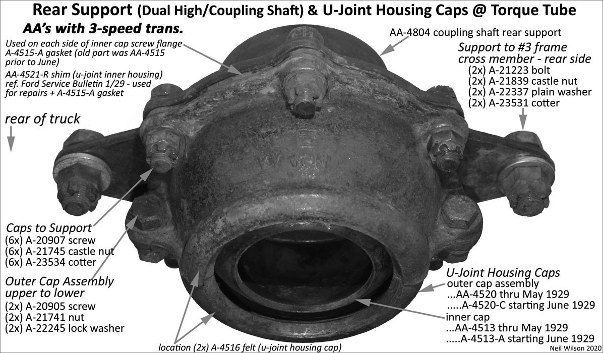
The inner and outer u-joint housing caps had equally space bolt holes. The outer assembly’s upper and lower caps were the same part.
Service part AA-4521-R was a shim made available starting December 1928. It was used to maintain correct spacing between the u-joint and inner cap (refer to the January 1929 Ford Service Bulletin).
Additional parts not covered by the coupling shaft parts group are shown in the table following.
Below is an image showing the inner and outer caps connection to the rear support of the dual high and coupling shaft.
| Coupling Shaft Assembly (AA’s with 3-speed trans.) – installation V1 @ torque tube | ||
|---|---|---|
| parts not covered by the coupling shaft parts group table | ||
| # | Part | Part Description (finish code) |
| Neil Wilson 2021 | ||
| VERSION 1 (V1) – for AA’s through Mar/Apr 1929 | ||
| 1 | AA-7090 d1 | U-Joint – 3/4″ wide riveted rings |
| A-chassis front knuckle; deep splined rear knuckle | ||
| 1 | ..A-7095 | Retainer (u-Joint front knuckle) 1.18″ diam. approx. |
| fasteners – U-Joint to coupling shaft | ||
| 1 | A-20905 screw 3/8-24 x 1” hex. head (u) | |
| 1 | A-22245 lock washer 3/8 (.401-.411 3/32 x 21/32) (u) | |
| 1 | AA-4513 | Cap (u-joint housing – inner) – no lubrication holes; equal spaced bolt holes |
| 2 | AA-4515 | Gasket (u-joint housing inner cap) equal spaced bolt holes |
| 2 | ..A-4516 | Felt (u-joint housing outer cap) |
| 1 | AA-4520 | Cap assembly (u-joint housing – outer) (bsg) equal spaced bolt holes |
| fasteners – cap assembly upper to lower | ||
| 2 | A-20905 screw 3/8-24 x 1 hex. head (u) | |
| 2 | A-21741 nut 3/8-24 (21/64 x 9/16) hex. (u) | |
| 2 | A-22245 lock washer 3/8 (.401-.411 3/32 x 21/32) (u) | |
| fasteners – caps to rear support & #3 frame cross member | ||
| 6 | A-20907 screw 3/8-24 x 1-13/32 hex. head (u) | |
| 6 | A-21745 castle nut 3/8-24 (13/32 x 9/16) (u) | |
| 6 | A-23534 cotter 3/32 x 1/8 (u) | |
| 1 | AA-4521-R | Shim (u-joint housing – inner) use for repairs + A-4515 gasket |
| available starting Dec/28 | ||
| AAAAAAAAA | aaaaaaaaaaaaaaaaaaaa aaaaaaaaaaaaaaaaaaaa aaaaaaaaaaaaaaaaaaaa aaaaaaa | |
Installation ttV2 starting Mar/Apr 1929
This ttV2 installation was used starting Mar/Apr 1929 until the 4-speed trans. was introduced in Aug/Sept 1929.
This installation is the same as the ttV1 installation above except for the re-designation of AA-chassis parts as A-chassis parts (includes A-4513-A, A-4515, A-4516, and A-4520-C.
More details regarding this part re-designation is found above under Installation 3sV4 above.
Additional parts not covered by the coupling shaft parts group are shown in the table to the right. This includes the re-designated parts.
Below is an image showing the inner and outer caps connection to the rear support of the dual high and coupling shaft.
| Coupling Shaft Assembly (AA’s with 3-speed trans.) – installation V2 @ torque tube | ||
|---|---|---|
| parts not covered by the coupling shaft parts group table | ||
| # | Part | Part Description (finish code) |
| Neil Wilson 2021 | ||
| VERSION 2(V2) – for AA’s starting Mar/Apr 1929 | ||
| 1 | AA-7090 d1 | U-Joint – 3/4″ wide riveted rings – thru July 1929 |
| A-chassis front knuckle; deep splined rear knuckle | ||
| 1 | AA-7090 d2 | U-Joint – 1-1/8″ wide riveted rings – starting August 1929 |
| A-chassis front knuckle; shallow splined rear knuckle | ||
| 1 | ..A-7095 | Retainer (u-Joint front knuckle) 1.18″ diam. approx. |
| fasteners – u-Joint to coupling shaft | ||
| 1 | A-20905 screw 3/8-24 x 1” hex. head (u) | |
| 1 | A-22245 lock washer 3/8 (.401-.411 3/32 x 21/32) (u) | |
| 1 | ..A-4513-A | Cap (u-joint housing – inner) with lubrication holes; equal spaced bolt holes |
| 2 | ..A-4515 | Gasket (u-joint housing inner cap) equal spaced bolt holes |
| 2 | ..A-4516 | Felt (u-joint housing outer cap) |
| 1 | ..A-4520-C | Cap assembly (u-joint housing – outer) (bsg) equal spaced bolt holes |
| fasteners – cap assembly upper to lower | ||
| 2 | A-20905 screw 3/8-24 x 1 hex. head (u) | |
| 2 | A-21741 nut 3/8-24 (21/64 x 9/16) hex. (u) | |
| 2 | A-22245 lock washer 3/8 (.401-.411 3/32 x 21/32) (u) | |
| fasteners – caps to rear support & #3 frame cross member | ||
| 6 | A-20907 screw 3/8-24 x 1-13/32 hex. head (u) | |
| 6 | A-21745 castle nut 3/8-24 (13/32 x 9/16) (u) | |
| 6 | A-23534 cotter 3/32 x 1/8 (u) | |
| 1 | AA-4521-R | Shim (u-joint housing – inner) use for repairs + A-4515 gasket |
| AAAAAAAAA | aaaaaaaaaaaaaaaaaaaa aaaaaaaaaaaaaaaaaaaa aaaaaaaaaaaaaaaaaaaa aaaaaaa | |
Page Contents