2024/03/08 update
Page Contents
*******TOC Dropdown – Tap/Click*******
Overview – AA Brake Systems
AA trucks had four brake system designs as follows:
- d1 – Trucks without emergency brakes (1927—1928)
- d2 – Trucks with emergency brakes (1929)
- d3 – AA131 trucks (1930—1932)
- d4 – AA157 trucks (5/30—12/32)
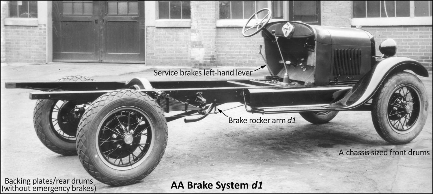
d1 Brake System – This system (shown in figure 1) included service brakes only (i.e. no separate emergency brakes). This design was used from 1927—12/28. A left-hand brake lever operated the service brakes. This design had an equalizer cross shaft installation similar to the A-chassis installation but with minor differences. The right/left brake shafts extended through the frame side members below the #2 cross member.
Rear brake linkage consisted of two rods on each side connected by a rocker arm. The steel front brake drums had a rolled flange and accommodated 11″ diameter x 1-1/2″ wide brake shoes. The steel rear brake drums had a rolled flange and accommodated 14″ diameter x 2-1/2″ wide brake shoes.
d2 Brake System – This system included both service brakes and separate emergency brakes and was used from late-1928—1929. However, the majority of 1928 AA’s used the d1 system. For d2, the prior equalizer cross shaft installation was replaced with a solid service brake cross shaft with end levers riveted in place. The center of the shaft was curved upward and over the coupling shaft. The cross shaft extended through the side members like the d1 system.
Rear brake linkage consisted of two rods on each side connected by a rocker arm.
The separate emergency brake system had a cross shaft installed on the backside of the #3 cross member. The front brake drums were the same as those used for d1. The steel rear brake drums had a flat flange. They were widened to accommodate the 14″ diameter x 1-1/2″ wide emergency brake bands.
d3 Brake System – This system was used for all AA131 chassis beginning January 1930. The system included a new straight service brake cross shaft with end levers riveted in place. It was installed under the frame near the front side of the #3 cross member. The steel front and rear brake drums were the same part and accommodated the 14″ diameter x 2-1/2″ wide service brake shoes with room for the rear 14″ diameter x 1-1/2″ wide emergency brake bands.
These drums had a flat flange. A heavy-duty AA brake pedal was used with this design.
There was a new emergency brake cross shaft which was located on the front side of the #3 cross member. AA’s with 1931 steel spoke wheels required unique front and rear brake drums.
d4 Brake System – This system was used for all AA157 trucks. It was a modified d3 system. The service and emergency brake cross shafts were in the same relative locations as the AA131. Consequently, these two cross shafts were 25-1/2″ further to the rear due to the longer frame. As a result, the brake pedal and emergency brake lever rods were longer. Front brake linkage consisted of two rods on each side connected by a rocker arm.
AA Brake Systems d1—d4 – covered by AA-chassis parts groups:
AA-1000 Wheels (Brake Drums only)
AA-2000 Service Brake
AA-2400 Service Brake Controls
AA-2600 Emergency Brake
AA-2800 Emergency Brake Controls
Note that the brake drums were part of the hub/drum assembly
which was in the AA-1000 wheels parts group.
Brake Drums
In the interest of safety, cast iron brake drums are allowed with a slight point deduction for RGJS judging.
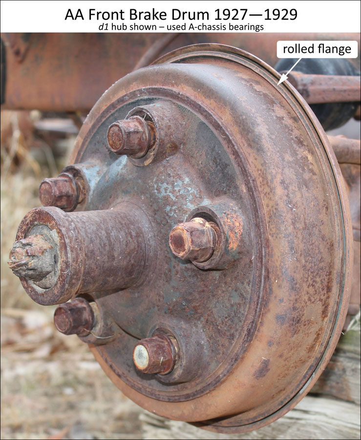
AA Front Brake Drums – The drums used through 1929, accommodated the A-chassis, 1-1/2″ wide by 11″ diameter brake shoes. These drums were attached to AA hubs and had a rolled steel flange. See figure 2a.
For AA’s with the five opening disk wheels (1930—1932), the AA front brake drums were identical to the rear drums and accommodated the larger 2-1/2″ wide by 14″ diameter brake shoes used on all AA rear brakes.
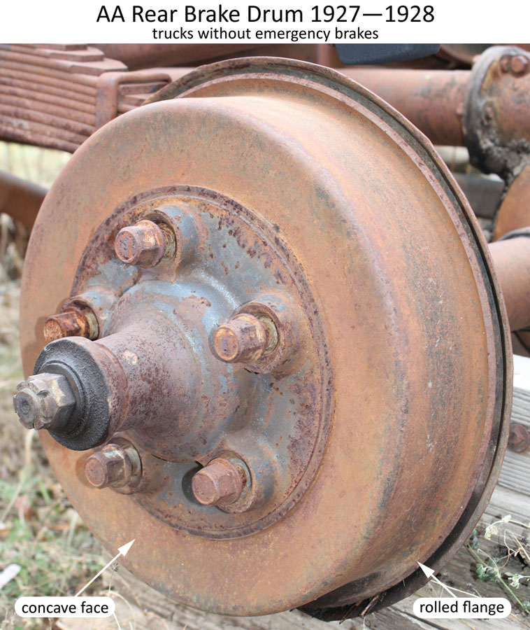
AA Rear Brake Drums – Trucks without emergency brakes had 2-1/2″ wide by 14″ diameter brake shoes. These steel drums had a rolled flange and a slightly concave face. See figure 2b.
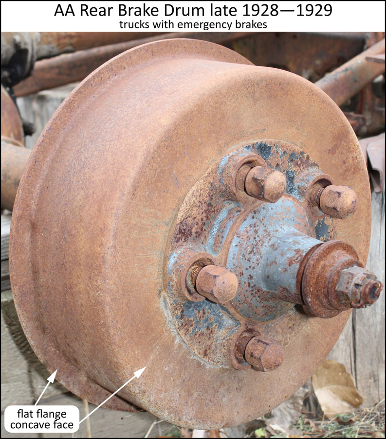
Through 1929, AA’s with emergency brakes had a wider drum to accommodate the 2-1/2″ wide service brake shoes and the 1-1/2″ wide emergency brake bands. These drums had a slight concave face. See figure 2c.
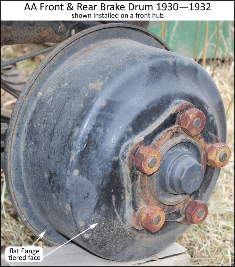
For 1930—1932, AA’s with the five opening disk wheels used identical front and rear drums with a tiered face. See figure 2d.
These drums accommodated the same size brake shoes and emergency brake bands as the prior 1929 rear drums.
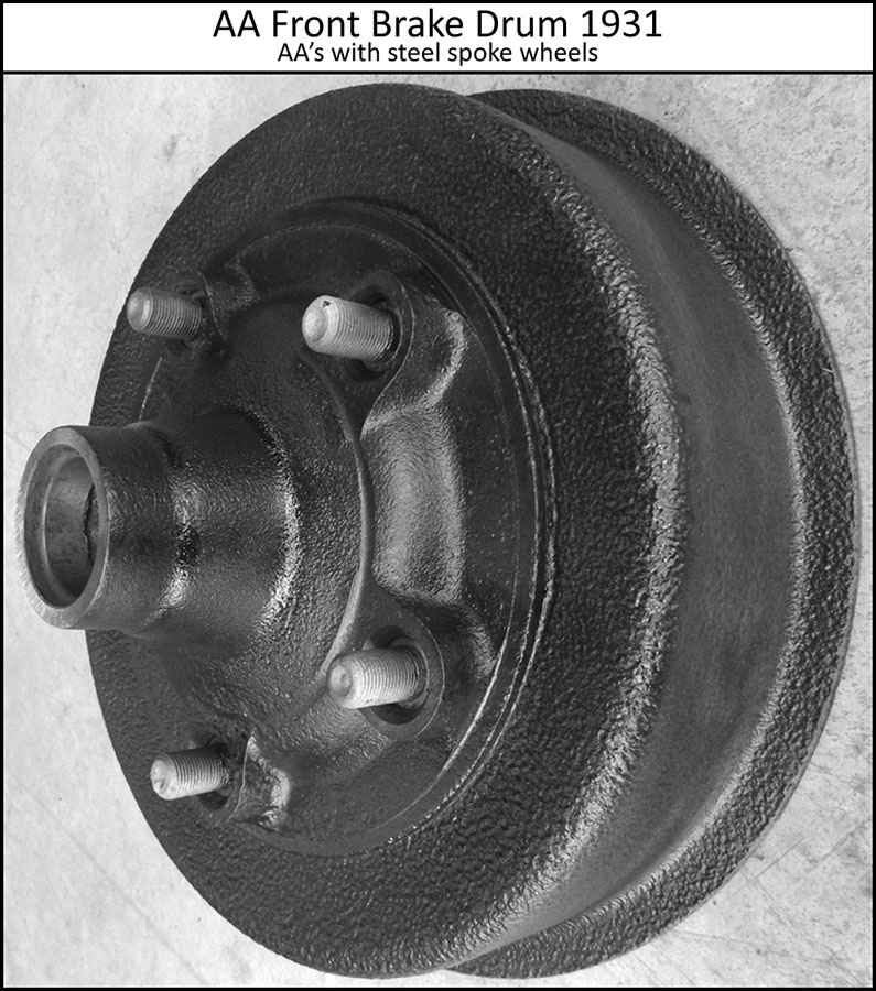
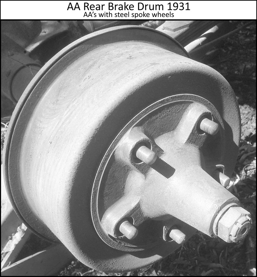
For AA’s with 1931 steel spoke wheels, the drums were unique due to having a larger hub bolt pattern. These drums also accommodated the same size brake shoes and emergency brake bands. See figure 2f.
Figures 2a—2f
Examples of AA brake drums
Brake Cross Shafts
Service Brake Cross Shaft
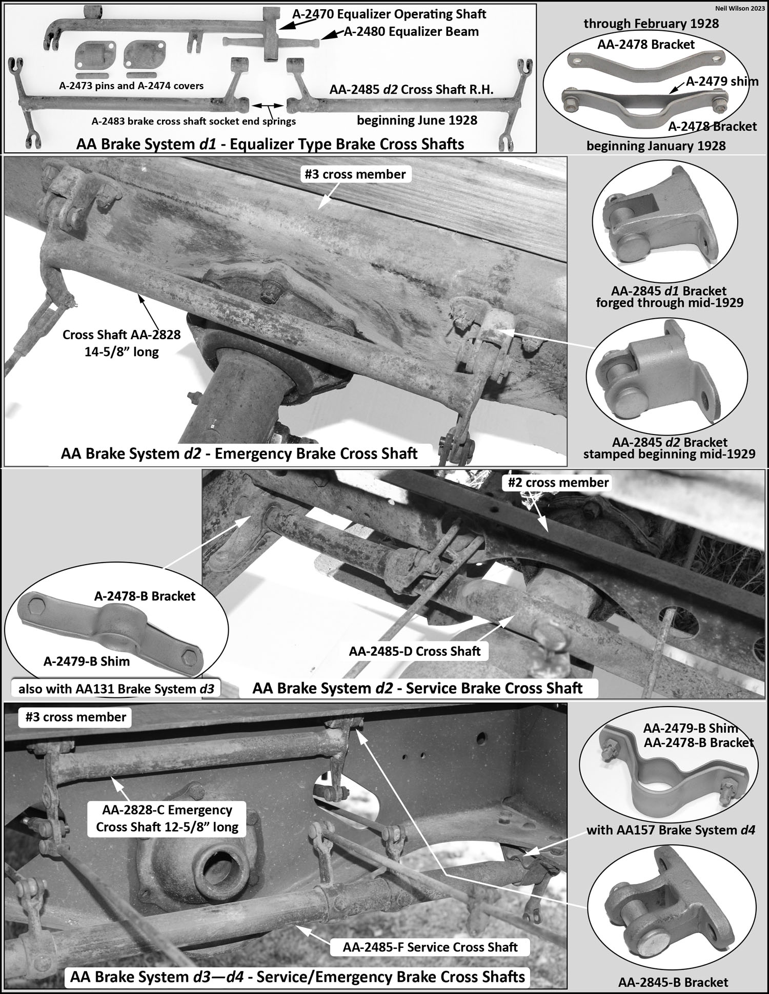
Brake system d1 – The initial service brake cross shaft installation was for trucks without emergency brakes. This installation included a brake equalizer operating shaft with a beam connecting the right and left brake shaft assemblies (parts AA-2485 & 2486). There were two designs of these shaft assemblies:
d1 – Each shaft had two levers that were pinned to the shaft. The end levers had an eye on the top for the rear brakes and a clevis on the bottom for the front brakes. These assemblies were used through May 1928. Front brake levers with an eye were used with these cross shaft levers.
d2 (see figure 3) – The two levers for each shaft were forged integral with the shaft. The end levers had a clevis on both the top and bottom.
These assemblies were used beginning in June 1928 and thereafter for AA trucks without emergency brakes. Front brake levers with a clevis were used with these cross shaft levers.
Brake system d2 (trucks with emergency brakes – through 1929) – The cross shaft shown in figure 3 was used. It was inserted through round openings in the frame side members prior to the installation of the end levers. Both the equalizer style cross shaft and this solid cross shaft used A-chassis front brake rods.
Brake system d3 & d4 (1930—1932) A new design straight cross shaft was used as shown in figure 3. This shaft was installed under the frame side members close to the front side of the #3 cross member. AA front brake rods (part AA-2501) were used with this shaft.
Service Brake Cross Shaft Installation
Brake system d1 – Trucks without emergency brakes used the following for installing the equalizer style brake cross shafts (R.F. = Raven Finish):
- AA-2478 brake cross shaft bracket – through 2/1928
- A-2478 brake cross shaft bracket and A-2479 shim – beginning in 2/1928
- A-20705 bolt – 5/16″-24 x 11/16″ hex head R.F.
- A-21702 nut – 5/16″-24 (11/64″ x 1/2″) hex R.F.
- A-22217 lock washer – 5/16″ (1/16″ x 27/64″) R.F.
For brake system d1 there were support brackets at cross member #2 that were riveted to the inside of the side members.
These brackets supported the #2, inverted “U” style, cross member. The bottom side of these support brackets were used to install the brake cross shaft brackets.
This positioned the cross shafts at the same location as the A-chassis cross shaft installation.
The cross shafts were inserted through oblong openings in the frame side members (inserted from the outside of the frame).
Brake system d2 – Trucks with emergency brakes used the following for installing brake cross shaft AA-2485-D:
- A-2478-B brake cross shaft bracket and A-2479-B shim (A-chassis parts)
- A-2477 bushing (A-chassis part)
- Through mid-1929
- A-20705 bolt – 5/16″-24 x 11/16″ hex head R.F.
- A-21702 nut – 5/16″-24 (11/64″ x 1/2″) hex R.F.
- A-22217 lock washer – 5/16″ (1/16″ x 27/64″) R.F.
- Beginning mid-1929
- A-20755 bolt – 5/16″-24 x 25/32″ hex head
- A-21701 castle nut – 5/16″-24 (21/64″ x 1/2″)
- A-23515 cotter – 1/16″ x 1/2″
The installation steps for the curved style AA-2485-D brake cross shaft were as follows:
- Bushing A-2477 was installed on each end of the cross shaft.
- Cross shaft was inserted through round frame openings from inside of the frame. Note that one side of the cross shaft had a longer machined lever shaft section which allowed the cross shaft to be installed via the inside of the frame.
- AA-2478 brackets and A-2479 shims were installed to hold the cross shaft.
- Right and left brake cross shaft levers (AA-2496-C and AA-2497-C) were installed with headless pins.
Beginning in late 1928, the #2 cross member support brackets were changed to eliminate the sections of the brackets below the cross shaft oblong opening in the frame. The oblong openings were changed to round openings for the new cross shaft.
Through early 1929, for AA’s with the inverted “U” style, #2 cross member, the brake cross shaft brackets and shims were installed under the #2 cross member support bracket (i.e. the same was done for the d1 brake system).
Beginning in early 1929, a new flat style #2 cross member was used and the support brackets were eliminated. The brake cross shaft brackets were bolted to the inside, lower flange, of the frame side members.
Brake system d3 – AA131 (1930—1932) used the following items for installing the brake cross shaft AA-2485-F:
- A-2478-B brake cross shaft bracket and A-2479-B shim (A-chassis parts)
- A-2477 bushing (A-chassis part)
- A-20755 short bolt – 5/16″-24 x 25/32″ hex head
- A-20838 long bolt – 5/16″-24 x 1″ hex head
- A-21702-S2 castle nut – 5/16″-24 (21/64″ x 1/2″)
- A-23515 cotter 1/16″ x 1/2″
The d3 brake system had a straight AA-2485-F cross shaft installed under the frame close to the front side of the #3 cross member.
Brake system d4 – All AA157 chassis used unique AA brackets and shims. Otherwise, the hardware was the same as used for brake system d3.
Emergency Brakes Cross Shaft
Brake system d2 – The cross shaft was installed on the backside of the #3 cross member. Through mid-1929, the cross shaft installation brackets were forged steel. Beginning in mid-1929, the brackets were stamped steel. See figure 3.
Brake system d3 & d4 – The cross shaft was installed on the front side of the #3 cross member. Forged steel installation brackets were used with this cross shaft. See figure 3.
Cross shaft assemblies included bushings for the shaft to bracket pin. The following installation hardware was used:
Bracket to frame:
- A-20936 bolt – 3/8″-24 x 15/16″ hex head
- A-21745 nut – 3/8″-24 (13/32″ x 9/16″) castle
- A-23536 cotter – 3/32″ x 5/8″ Zink plated
Cross shaft to bracket:
- A-23890 pin – 7/16″ x 1-21/32″ button head (1-3/8″ long pin for brake system 2 also used)
- A-23533 cotter – 3/32″ x 1″
In late 1928, Ford offered a replacement, solid, brake cross shaft for prior AA’s with the brake equalizer style cross shaft. This was a service only part and would not be original for judging purposes.
Front Brake Shaft Assemblies
Through 1929, the front brake shaft assembly (which included the lever) was the same as those used on the A-chassis. Refer to RGJS Area 7. Beginning in January 1930 the front brake-actuating lever AA-2084 was used as part of the shaft assembly. This AA lever is shown in figure 4.
Rear Brake Actuating Levers
The rear levers use to activate the service and emergency brakes are shown in figure 4.
Rear Service Brake Levers
The rear brake cam shaft extensions (levers) used to activate the service brakes are shown in figure 4.
The ball end of the extension had a felt dust ring next to the lever. The ball was then fit into a socket in the rear radius rod. On the inside of the radius rod was a drive-in, plain type lubricator fitting. The splined end of the lever fit into the cadmium plated cam shaft (only the end of cam shaft can be seen).
The lever was angled about 15° to the rear when the brakes were released. To keep the extension snug in the radius rod sockets, spring AA-2233 was placed in the splined end of the extension. The spring pushed against the cam when installed. The spring cannot be seen.
For trucks without emergency brakes (through 1928), part AA-2238 was an assembly consisting of a lever pinned to a 7-1/2″ long extension shaft. For trucks with emergency brakes, the lever was integral with the three styles of 6-3/4″ long extensions.
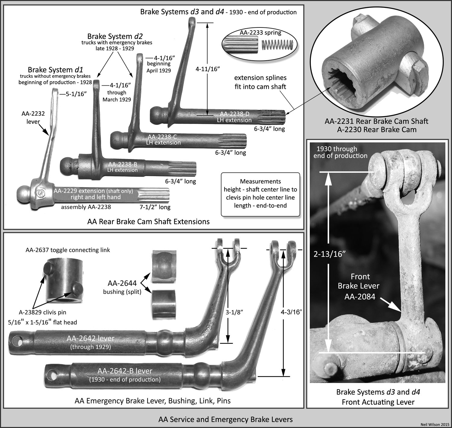
Emergency Brake Levers
The emergency brake levers used to activate the emergency brake bands are shown in figure 4.
Levers were connected to toggle levers with connecting links (sleeves). The end of the toggle lever extended out the backside of the backing plate. Once the sleeve was in place, the toggle lever could not be seen.
Each lever had a split brass bushing inserted through a hole in the rear radius rod. The bushing was a hand pressure fit. The connecting link was then pinned to both the activating lever and to the toggle lever.
Brake & Clutch Pedals
An AA brake pedal was used with the d3 and d4 AA brake systems beginning in January 1930.
Both the pedal-to-shaft section (lower section) and the foot rest section were the same as the corresponding sections of the two piece forged designed A-chassis pedal. The AA pedal’s center section was of a heavier design. This heavier design required a unique AA #1 floor board with a relief (grove) on the bottom (back) side that provided pedal clearance.
For AA’s with a four-speed transmission, the clutch pedal had a three coil retracting spring anchored to the pedal shaft collar pin. See the “Brake System Retracting Springs” section for more information.
Otherwise, the brake and clutch pedals were the same as those used for the A-chassis and details are found in the RGJS Area 7.
Backing Plates (Brake Housings)
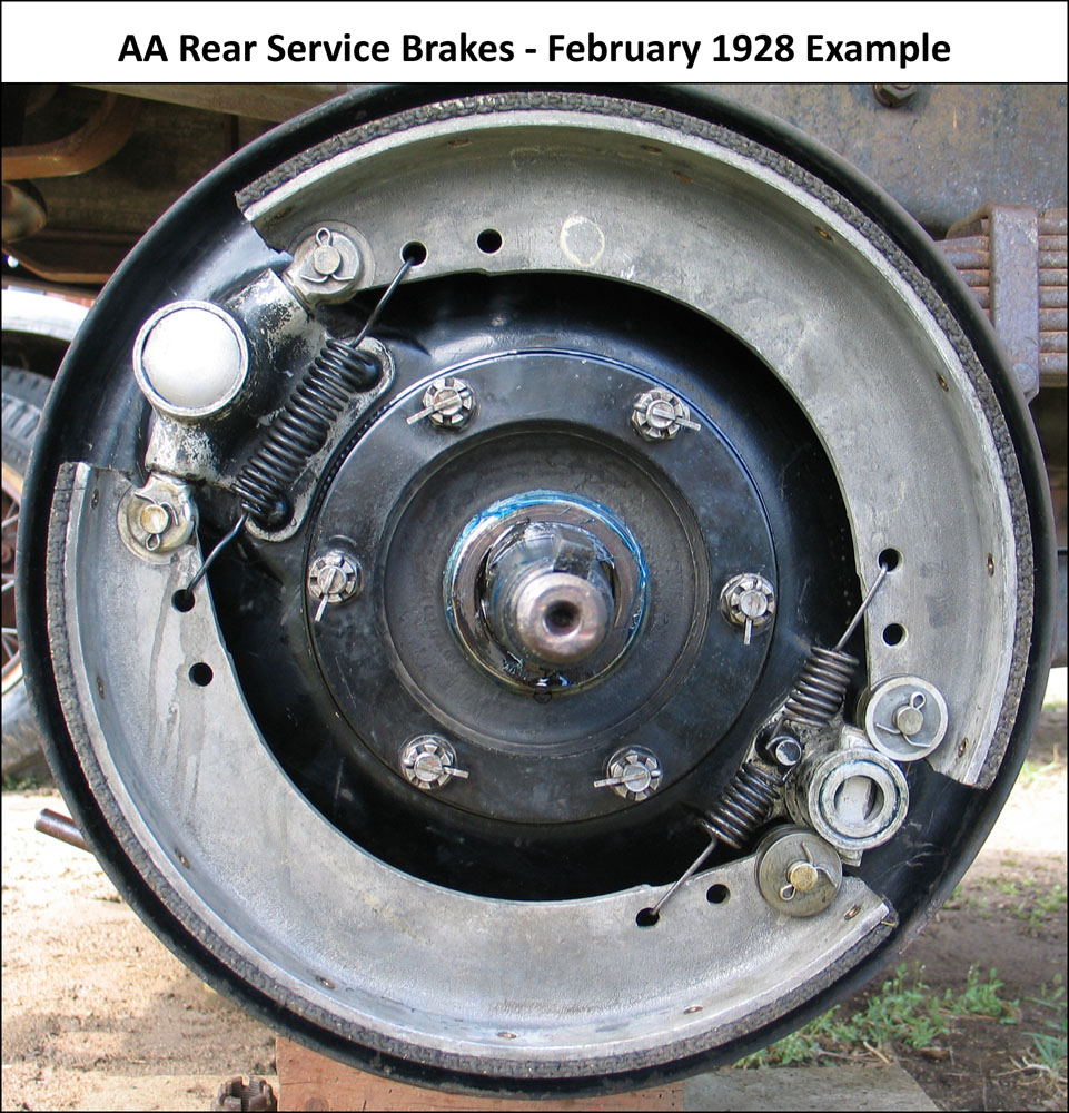
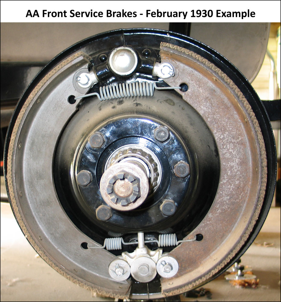
Examples of service brakes installed on backing plates are shown in figure 5a and 5b. Note that the 1930 front brake example has the same size brake shoes as rear AA brake shoes.
Backing plates were installed with unfinished hardware. All backing plates were dipped, gloss black enamel prior to installation of the cadmium plated brake adjusting wedge and lower wedge stud.
Front Backing Plates
Through 1929, front backing plates were the same as those used on the A-chassis. Refer to RGJS Area 7.
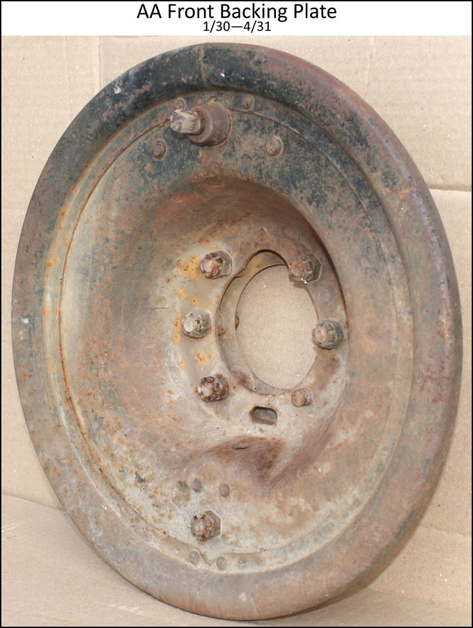
Beginning in January 1930 AA front backing plates were introduced with the d3 brake system for use with larger front brake drums. These drums were the same as the rear brake drums. The initial AA front backing plate assemblies included two-piece dust shields that were riveted and spot-welded to the stamped steel backing plate. See figure 6a.
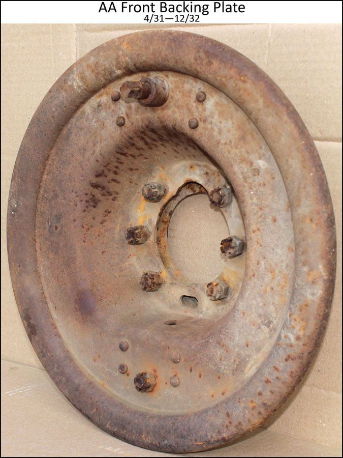
Beginning in April 1931, one-piece front backing plates were introduced. The dust shield was an integral part of the plate stamping. See figure 6b.
Rear Backing Plates
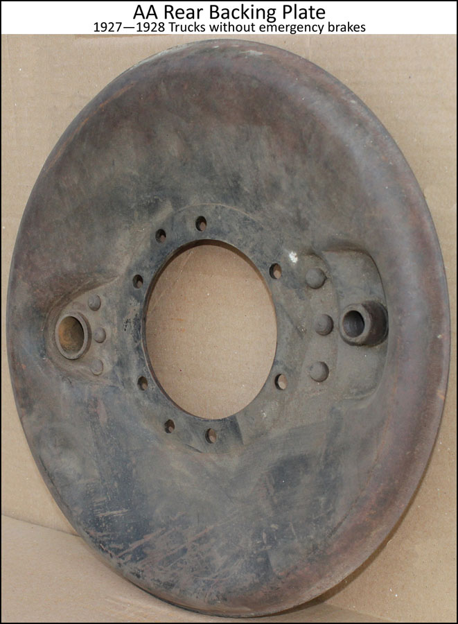
The d1 brake system (for trucks without emergency brakes) used a stamped steel backing plate that curved around the brake drum like the A-chassis backing plates. See figure 6c.
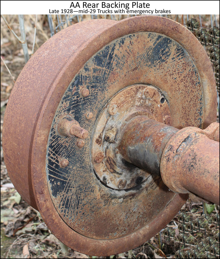
The d2 brake system (for trucks with emergency brakes) used a 1/4″ thick flat steel rear backing plate without dust shields. See figure 6d.
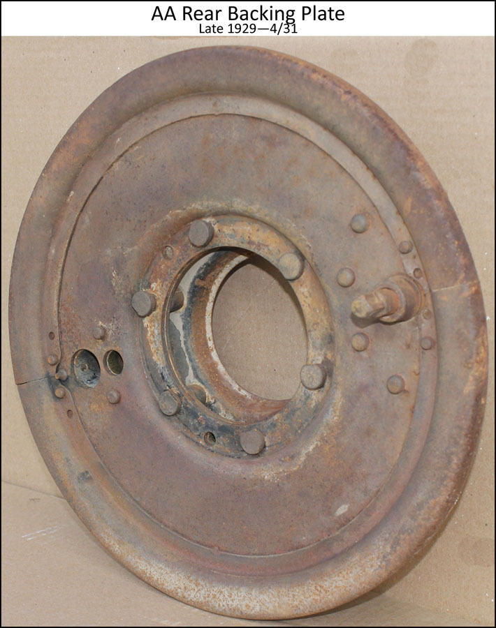
Beginning in late 1929, two-piece dust shields were riveted and spot-welded to the backing plates. These plate assemblies were used with the d3 and d4 brake system through May 1931. See figure 6e.
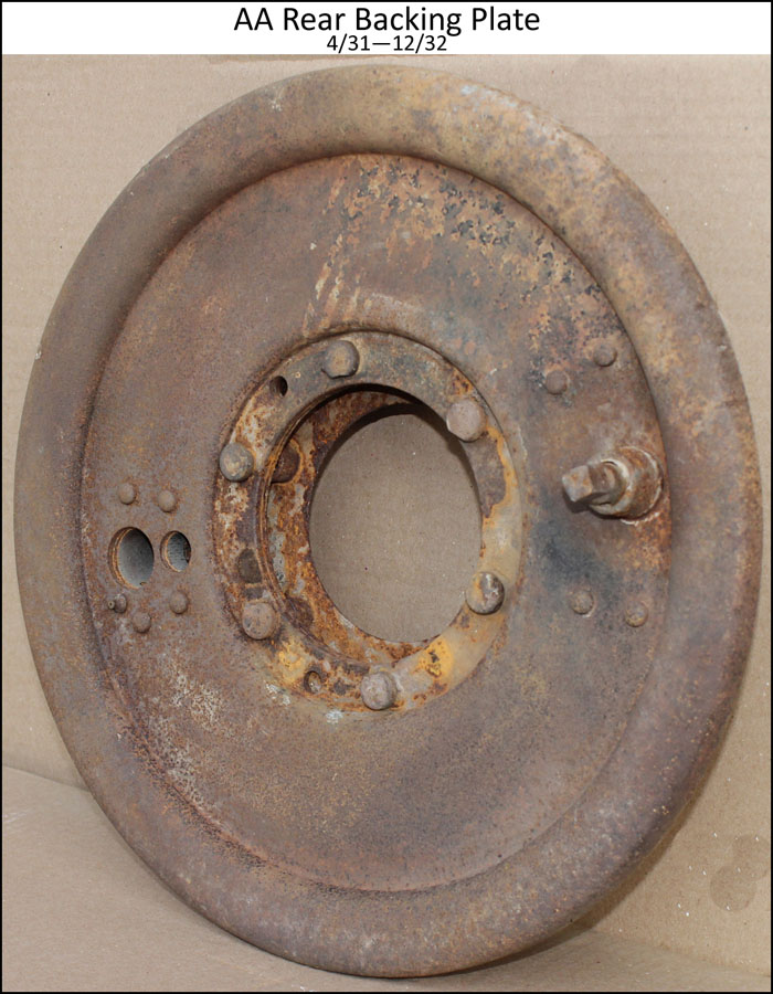
In April 1931, one-piece rear backing plates were introduced. The dust shield was an integral part of the backing plate stamping. See figure 6f.
Brake Rocker Arms
Rocker arms were finished with black enamel and installed with unfinished hardware.
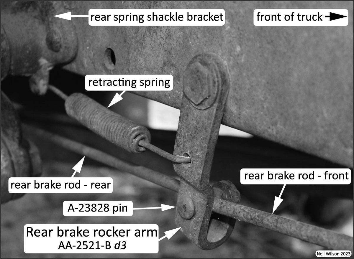
All 1928—1929 AA-chassis had two brake rods on each side making up the linkage to the rear brakes from the service brake cross shaft. The two rods were joined several inches forward of the rear spring shackle bracket with a rear brake rocker arm.
The arms were bolted to the frame with shoulder bolts that allowed them to swing forward when the brakes were applied.
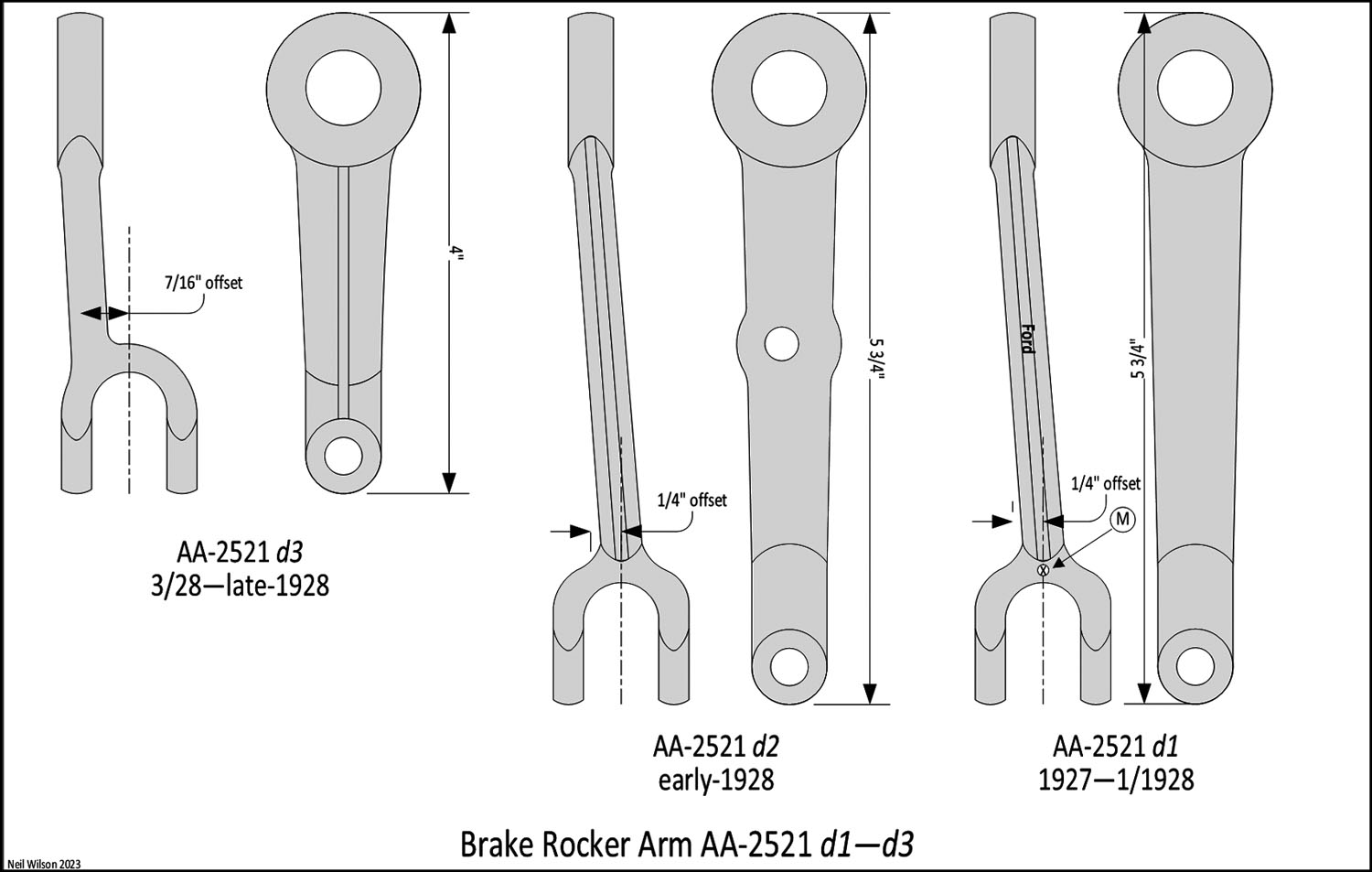
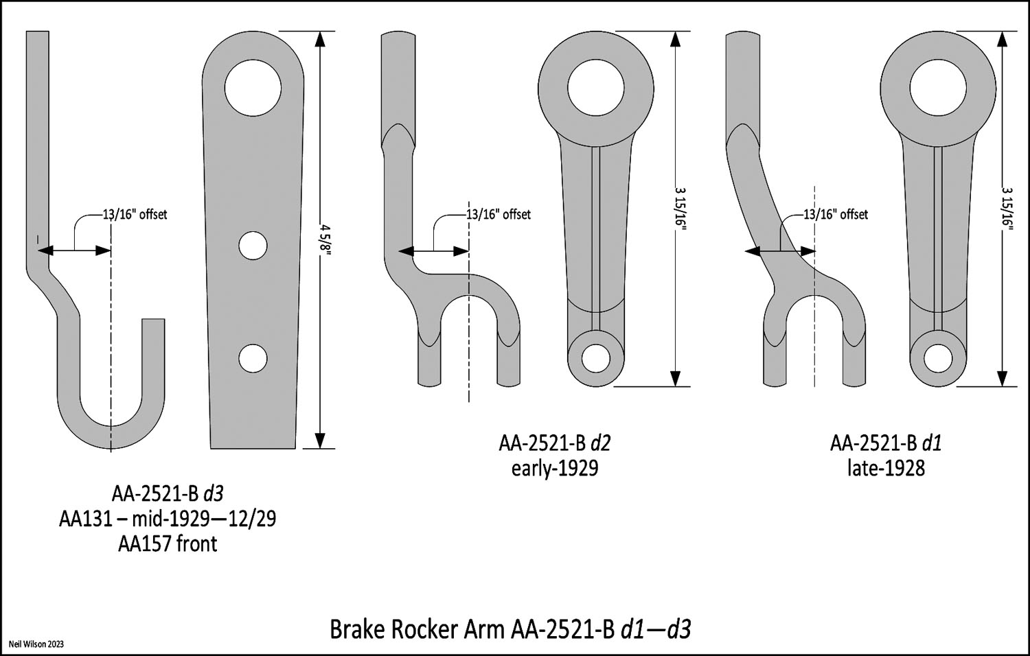
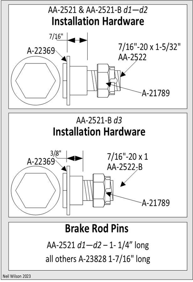
There were six styles of rear brake rocker arms as shown in figures 7 and figures 8. The installation hardware is shown in figure 9 and lists the brake rod pins used.
An example installation of the AA-2521-B d3 rocker arm is shown in figure 10. This rocker arm was also used on the AA157 for the front brakes, two-brake-rod linkage. No retracting spring was used for the AA157 installation.
All rocker arms were forged steel except for the stamped steel AA-2521-B d3 rocker arm.
Brake Rods
The brake rods tables provides a breakdown of both service and emergency brake rods used by each of the four AA brake systems. Finish of brake rod parts were:
- Brake rod – black enamel
- Check nut (3/16″ x 1/2″) – unfinished
- Adjustable clevis and eye – black enamel
For AA brake system d1 (AA’s without emergency brakes), both the brake pedal and hand brake lever used rod A-2465. This A-chassis rod had an elongated hole for the pin which allowed both rods to operate the service brakes independently.
Due to the location of the service brake cross shaft for brake systems d2, d3 and d4 (AA’s with emergency brakes), each system required different length brake pedal to cross shaft rods.
Note that AA’s with a four-speed transmission had two designs of brake stop light switch operators installed on the pedal to cross shaft rod. These installations are in the 13510 – Electrical part group.
Brake Rods Tables d1—d4
Brake System Retracting Springs
For the equalizer type brake cross shafts, there were A-2483 brake cross shaft socket end springs. The internal location of these springs is indicated in figure 3 (upper left image). Sorry, no photo.
The internal AA-2233 cam extension end spring is shown in figure 4.
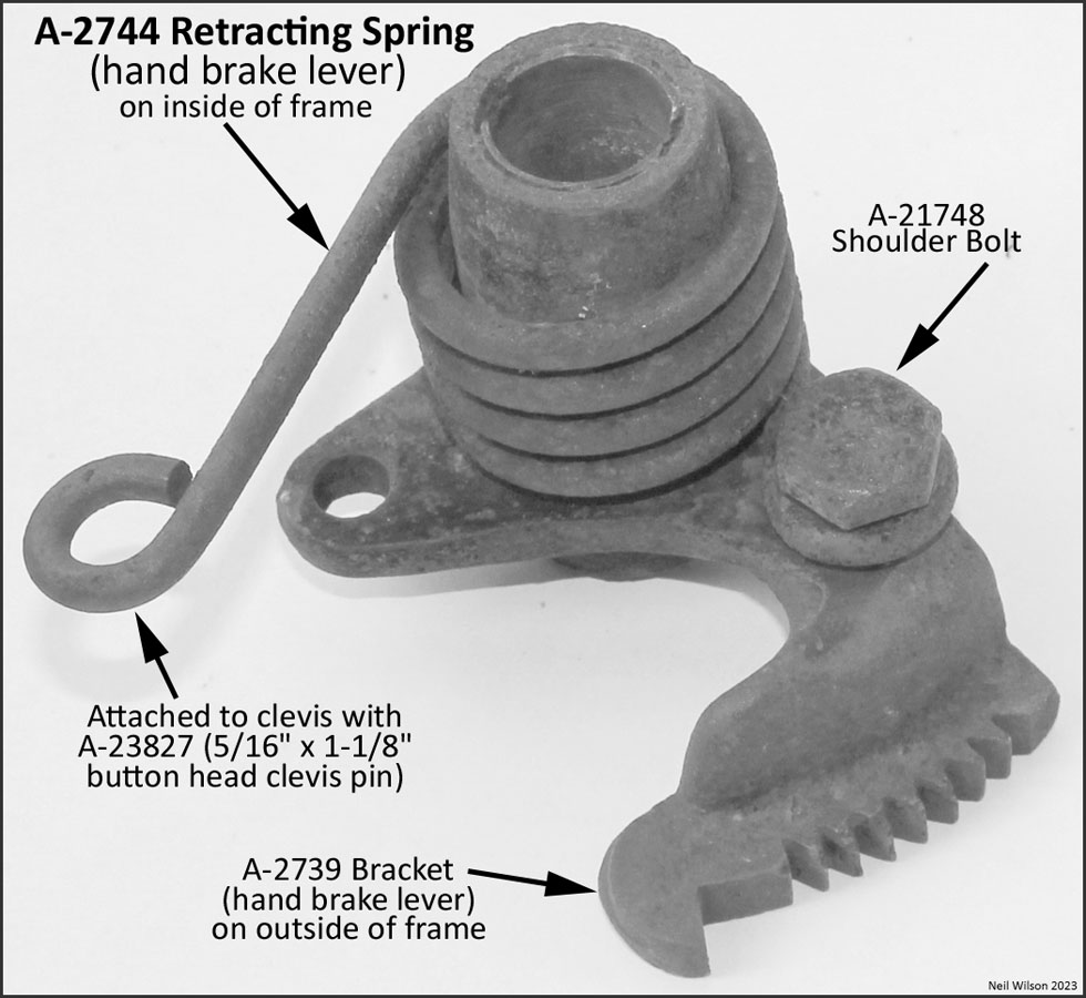
The hand brake lever of the d1 AA brake system had an A-2744 five-coil, black enameled retracting spring as shown in figure 11. The spring was installed on the inside of the frame around the A-2739 bracket shaft housing. One end of the spring was attached to the frame with shoulder bolt A-21748. The other end of the spring was attached to the hand brake rod clevis with pin A-23827 (5/16″ x 1-1/8″ button head clevis pin).
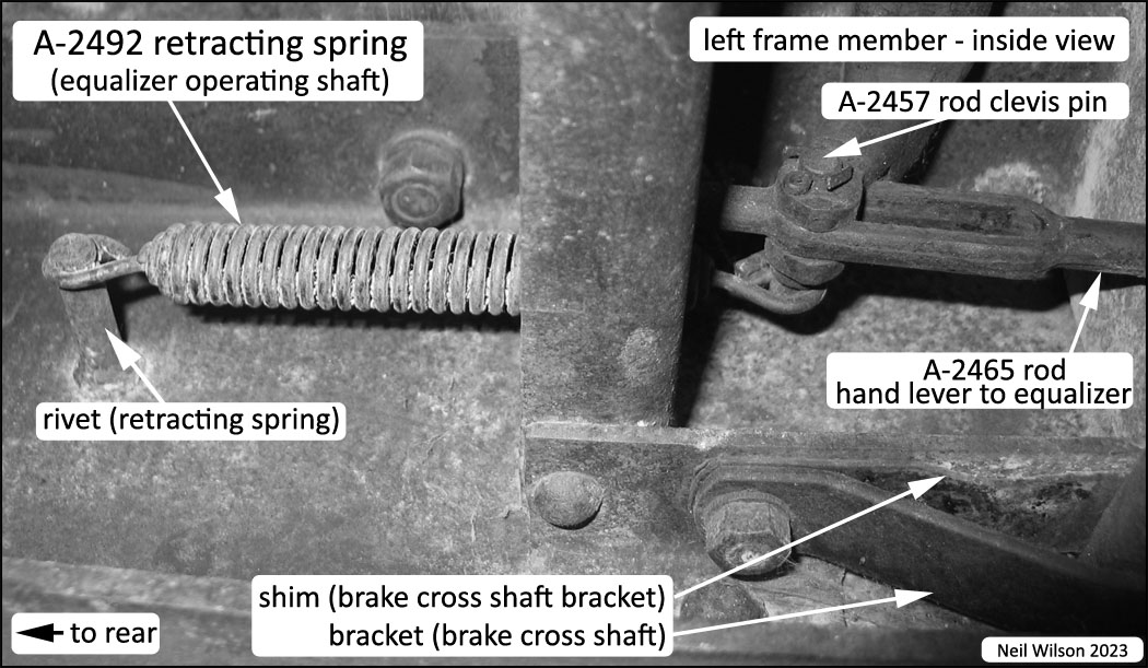
For the d1 AA brake system there was A-2492 retracting spring as shown in figure 12. It was hooked to the hand-lever-to-equalizer-rod pin and to a rivet attached to the inside of the frame. The spring was black enameled and used through February 1928.
In December 1927, front brake rod springs were added. For installation of these springs, the front brake rods were redesigned to have a button to fit the spring pocket and A-2504 brake rod spring brackets were added to the frame.
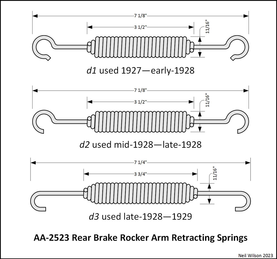
Beginning in January 1928, rear brake rocker arm retracting springs were added. The various spring designs are shown in figure 13.
These springs were finished in black enamel. For installation of these springs a lobe was added to the bottom-center of each shackle bracket and a hole was added to the brake rocker arms (see figure 7 part AA-2521 d2). See figure 10 for an example of this spring installation.
With the addition of separate emergency brakes, a bracket was added to each rear radius rod for installation of emergency brake rod retracting springs. With the change to the d3 AA brake system in January 1930, service brake rod retracting springs were installed on the same rear radius rod brackets.
All brake rod retracting springs were black enameled and were the same as those used on the A-chassis (refer to RGJS Area 7 for details of the six designs of these springs).
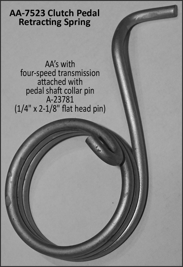
The AA-7523, three coil, black enameled, clutch pedal return spring is shown in figure 14. This spring was used for AA’s with a four-speed transmission. It was anchored to unfinished pedal shaft collar pin A-23781 (1/4″ x 2-1/8″ flat head pin).
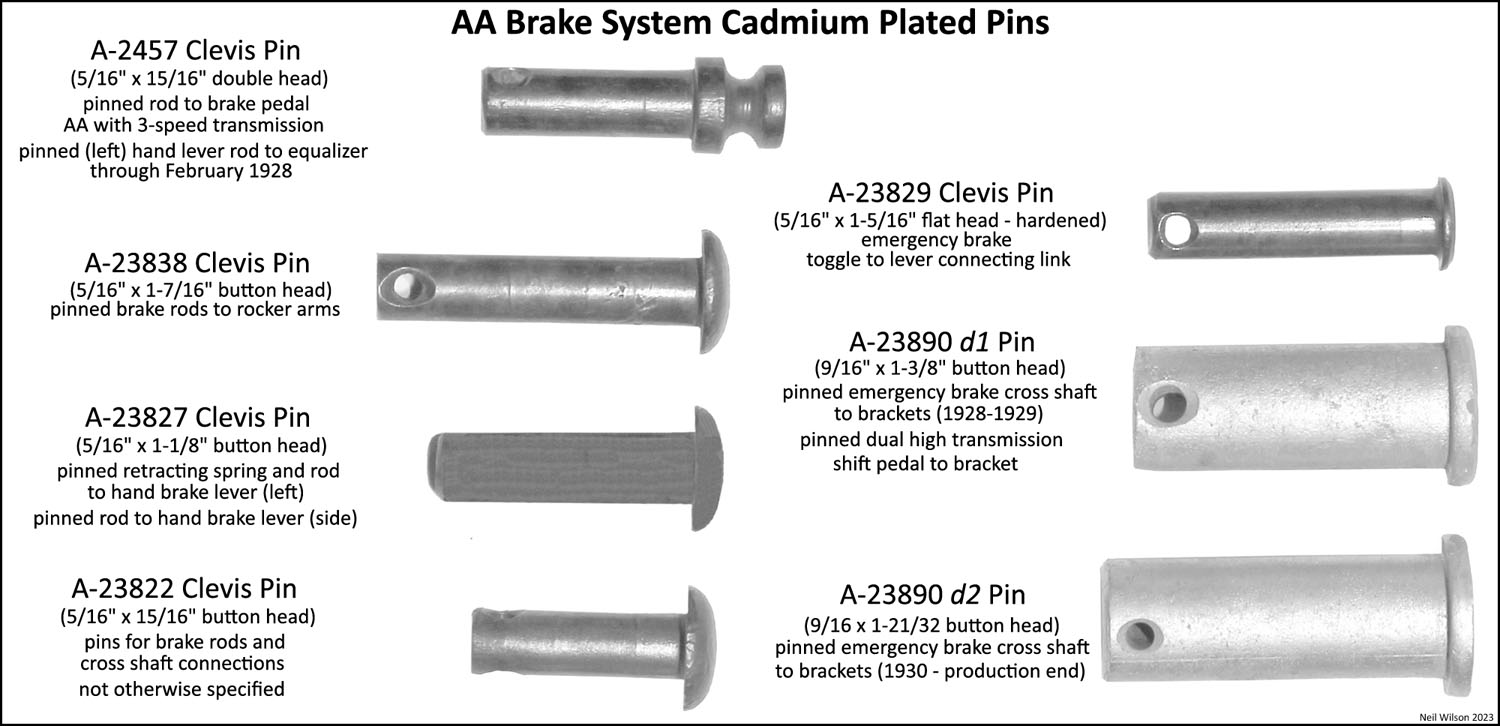
Brake System Pins
The pins used for the AA brake systems are shown in figure 15.
The double headed clevis pin A-2457 accommodated attaching the brake light switch link for an AA-chassis with the A-chassis 3-speed transmission. This pin also accommodated attaching the equalizer operating shaft retracting spring used through February 1928.
The A-23838 clevis pin was used for all brake rod rocker arms (rear rocker arms through 1929 and front rocker arms for AA157).
The A-23827 clevis pin was used for the attachment of the hand brake lever retracting spring to the rod elongated hole of the left-side hand service brake lever. For AA’s with a right-side emergency brake hand lever, this pin was also used to attach the front clevis of the “hand lever to emergency brake cross shaft rod”.
Clevis pin A-23822 was used for the AA brake systems excepted as otherwise listed.
Clevis pin A-23839 was used for the installation of the emergency brake connecting link (i.e. the sleeve connecting the toggle lever to activating lever)
Clevis pin A-23890 had two designs as follows:
d1 – 1-3/8″ long pin was used to attach the emergency brake cross shaft to the shaft brackets for the d2 AA brake system. This pin was also used to attach the dual high transmission shift pedal to its frame-mounted bracket.
d2 – 1-21/32″ pin was used on AA brake systems d3 and d4. It was used to attached the emergency brake cross shaft to the forged shaft brackets.