2023/12/01 update
Page Contents
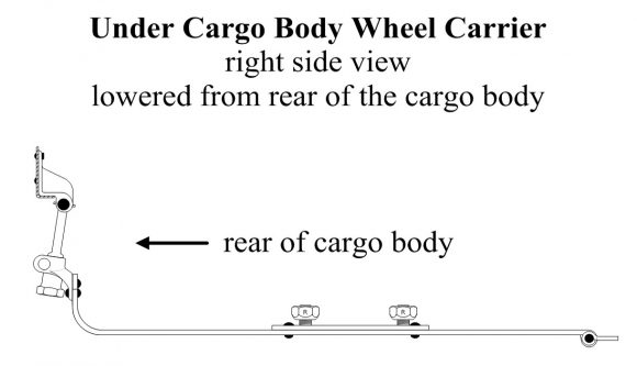
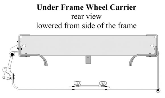
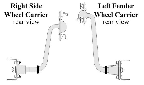
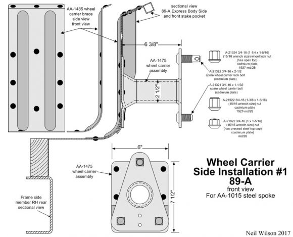
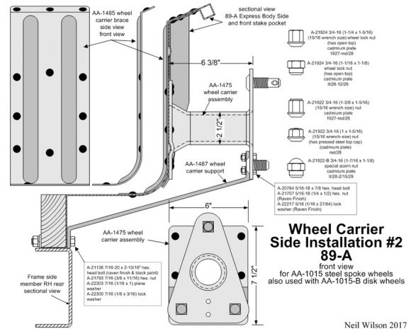
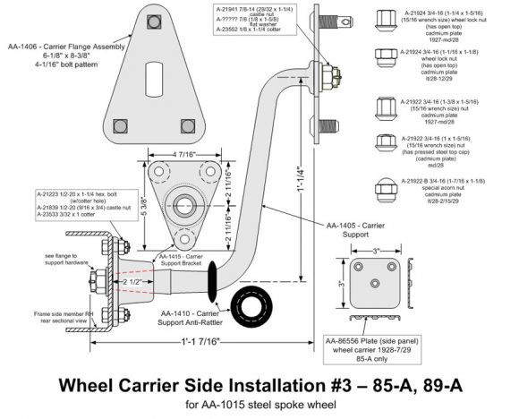
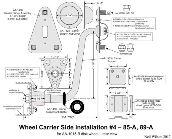
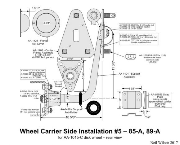
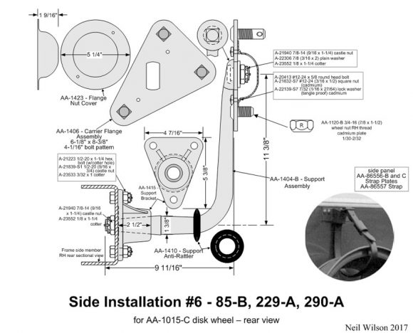
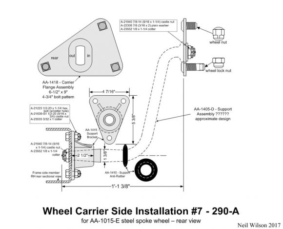
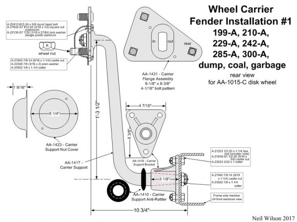
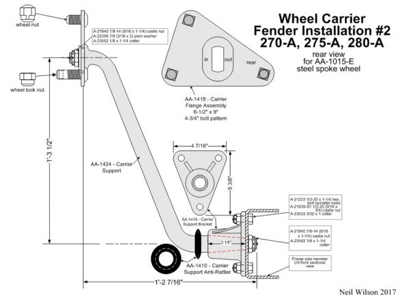
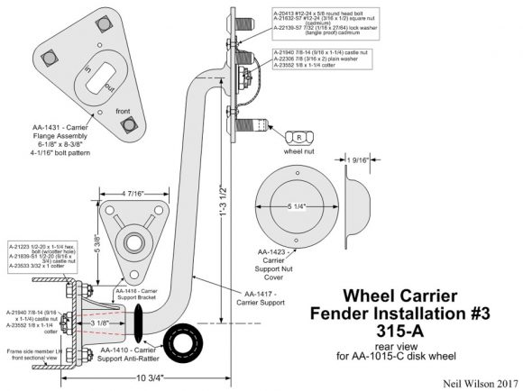
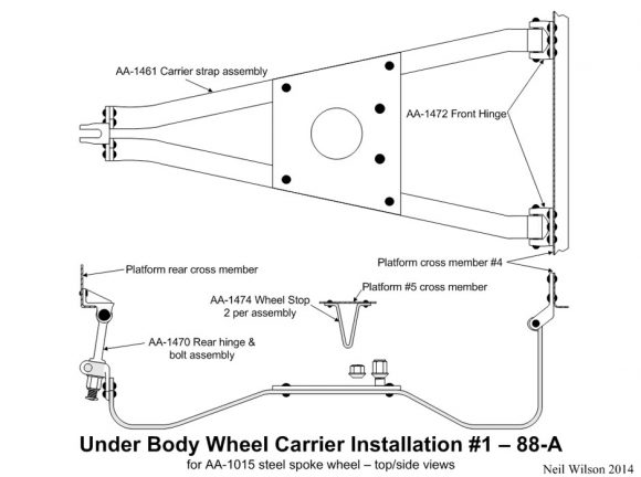
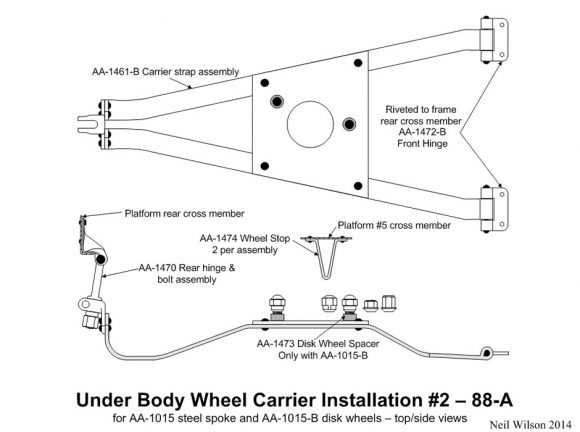
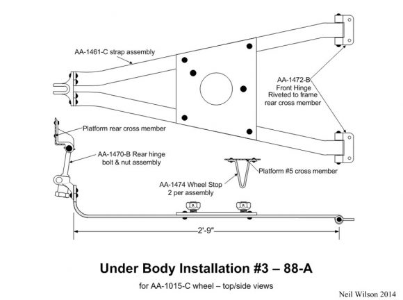
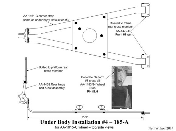
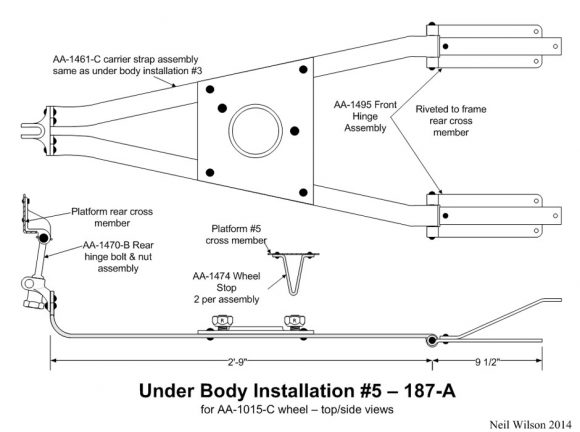
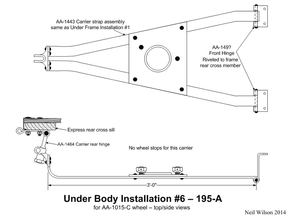
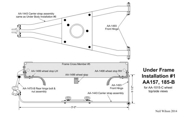
The examples above show AA wheel carrier installation types. The Installation Table below lists the carrier installation for each body type. Some body types had multiple carrier installations and some had none.
Installation details are found in the Side & Fender Carriers or Under Body & Frame Carriers galleries.
Table Notes
Side carriers were installed on the right side putting the spare on the running board and back of the front door. Fender carriers were installed at the left or right front fender. Note the view orientations of the examples at the top of the page. For many body types, AA’s with a closed cab and left fender carrier installation, had a left door indentation providing tire clearance.
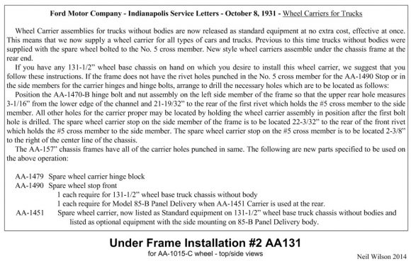
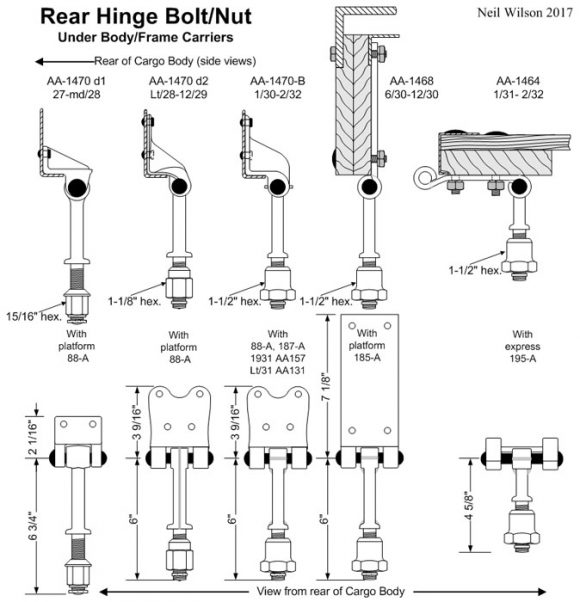
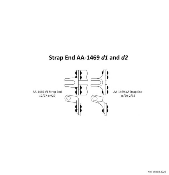
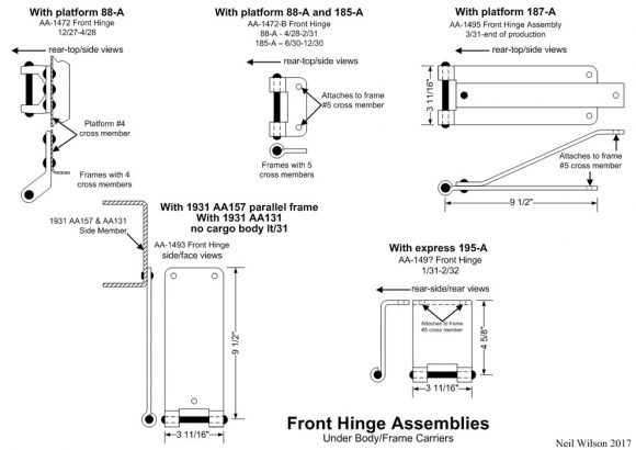
Under body carriers were installed under the cargo body at the rear and were lowered from the rear. Under frame carriers were installed under the rear of the chassis frame and were lowered from the side.
Side & Fender Wheel Carrier Installations Gallery
Under Body & Under Frame Wheel Carriers Installations Gallery
Wheel Carrier Finishes
Carrier parts riveted or bolted to the cargo body were painted body color. This would include body mounted side carrier installations 1 and 2 (89-A express). Also, body color was used for under body carrier installation 1 which was mounted to the 88-A platform. All under body carrier installations had the rear hinge and bolt assembly and wheel stops attached to the platform body and were finished body color.
Carriers riveted to the frame were painted black with the frame. Side and fender carriers bolted to the frame were painted unassembled in black enamel.
Any special chassis color would have covered the original black of these carriers.
The check nuts of the rear hinge and bolt assemblies (shown in the Under Body & Frame Carriers Installations Gallery ) were cadmium plated. These check nuts were either painted with the assembly or masked off and left unpainted.
Carrier flange wheel studs were cadmium plated and then painted with the carrier flange after assembly.
The nut cover was painted black and the attachment hardware was finished as follows:
- A-20413 #12-24 x 5/8 round head bolt (unfinished)
- A-21632-S7 #12-24 (3/16 x 1/2) square nut (cadmium)
- A-22139-S7 7/32 (1/16 x 27/64) lock washer (tangle proof) cadmium
For side and fender support brackets which were bolted to the frame – the unfinished attachment hardware was as follows:
- A-21223 1/2-20 x 1-1/4 hex bolt (w/cotter hole)
- A-21839 1/2-20 (9/16 x 3/4) castle nut
- A-23533 3/32 x 1 cotter
Side and fender support to support bracket and support to wheel flange hardware was unfinished. Hardware was as follows:
Side Installation 3 and 4
- A-21941 7/8-14 (29/32 x 1-1/4) castle nut
- A-????? 7/8 (1/8 x 1-5/8) flat washer
- A-23552 1/8 x 1-1/4 cotter
Side Installation 5 – 7 and Fender Installations
- A-21940 7/8-14 (9/16 x 1-1/4) castle nut
- A-23552 1/8 x 1-1/4 cotter
Page Contents

