
2024/02/18 update
By Brian Jensen – Late 2023
Covers #1 (slant) and #2 (flat) floor board designs.
Page Contents
Figures List
- Fig 1 – Linderman dovetailing machine
- Fig 2 – Board dimensions and orientation
- Fig 3 – Dovetail dimensions
- Fig 4 – Dovetail router bit
- Fig 5 – Making the groove
- Fig 6 – Making the dovetail
- Fig 7 – Clamping the boards
- Fig 8 – Cutting the edge bevels
- Fig 9 – Drilling the dowel holes
- Fig 10 – Dowels installed
- Fig 11 – Fitting up in the cab
- Fig 12 – Floor board #2 features (underneath view)
Figures List Cont.
- Fig 13 – Floor board #1 features (underneath view)
- Fig 14 – Steps to create features
- Fig 15 – Brake and clutch slots
- Fig 16 – Accelerator pedal hole and clearance
- Fig 17 – Clearance for brake equalizer cover
- Fig 18 – Dual high holes and clearance
- Fig 19 – Marking holes for welting
- Fig 20 – Welting mark
- Fig 21 – Punching welting hole
- Fig 22 – Underneath of finished floor board #2
- Fig 23 – Finished floor boards installed in cab
Introduction
This article is written to assist those wishing to reproduce their own floor boards for the Model A Ford. From the beginning of production and into 1929, Model A floor boards were made by assembling several hardwood boards together side-by-side to make a solid wooden floor, or “floor boards” for the vehicle. These floor boards utilized dovetailed and glued edge joints between the boards for strength.
The hardwood floor boards illustrated in this article were made for an early 1928 AA 82-A closed cab truck. Many of the techniques used to create these floor boards may be utilized to make the floor board features for other Model A’s and AA’s.
Generally, the Model A pickup with closed or open cab and the A panel delivery used the same floor boards as the Model AA commercial trucks with cab or AA panel delivery.
During 1929, hardwood floor boards were gradually replaced with plywood versions that were used for the remainder of production. Those wishing to create plywood floor boards will skip the dovetailing and assembly steps but can utilize the steps for sizing, creating features, finishing and welting.
Before beginning, you should determine the specific requirements for your floor boards in terms of materials, dimensions and features for your vehicle.
Whether reproducing floor boards for cars or trucks, the following areas should be referenced within the Model “A” Ford Judging Standards & Restoration Guidelines(1) to determine the specific changes through production and how they apply to your vehicle:
Area 11 – Carpets and Mats
Supplement A – Early 1928 Vehicles
Supplement E – Heavy Commercial Vehicles.
For Model AA commercial trucks there is a great deal of information available in the Floor Boards page on the AAfords.com site(2).
This same information is within two AA Truck Talk technical articles written by Neil Wilson and published in The Double A’er newsletter(3). Much of this information can also be used for the pickup, A panel delivery and cars.
Preparing The Boards
For all floor boards, you need to start with a “blank” piece of material large enough to cut the floor board from.
If using plywood, the floor board profile is simply cut from a sheet of plywood larger than the floor board. The plywood specifications on the original Ford drawing were to be 11/16 inch thick “5-ply fir”.
If using solid hardwood, the blank must first be created by joining several boards together until the resulting blank is larger than the floor board.
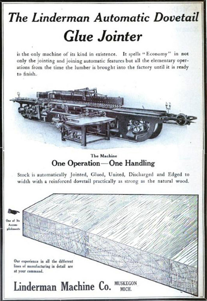
Ford’s production process utilized a Linderman machine to mass-produce the floor board “blanks” by dovetailing, gluing and assembling the hardwood boards all in one machine. Figure 1 shows a vintage advertisement for the Linderman machine(4).
The hardwood specified by the original Ford drawing was “maple, beech, birch, elm or oak” and the boards were to be “free from full knots, checks and warp”.
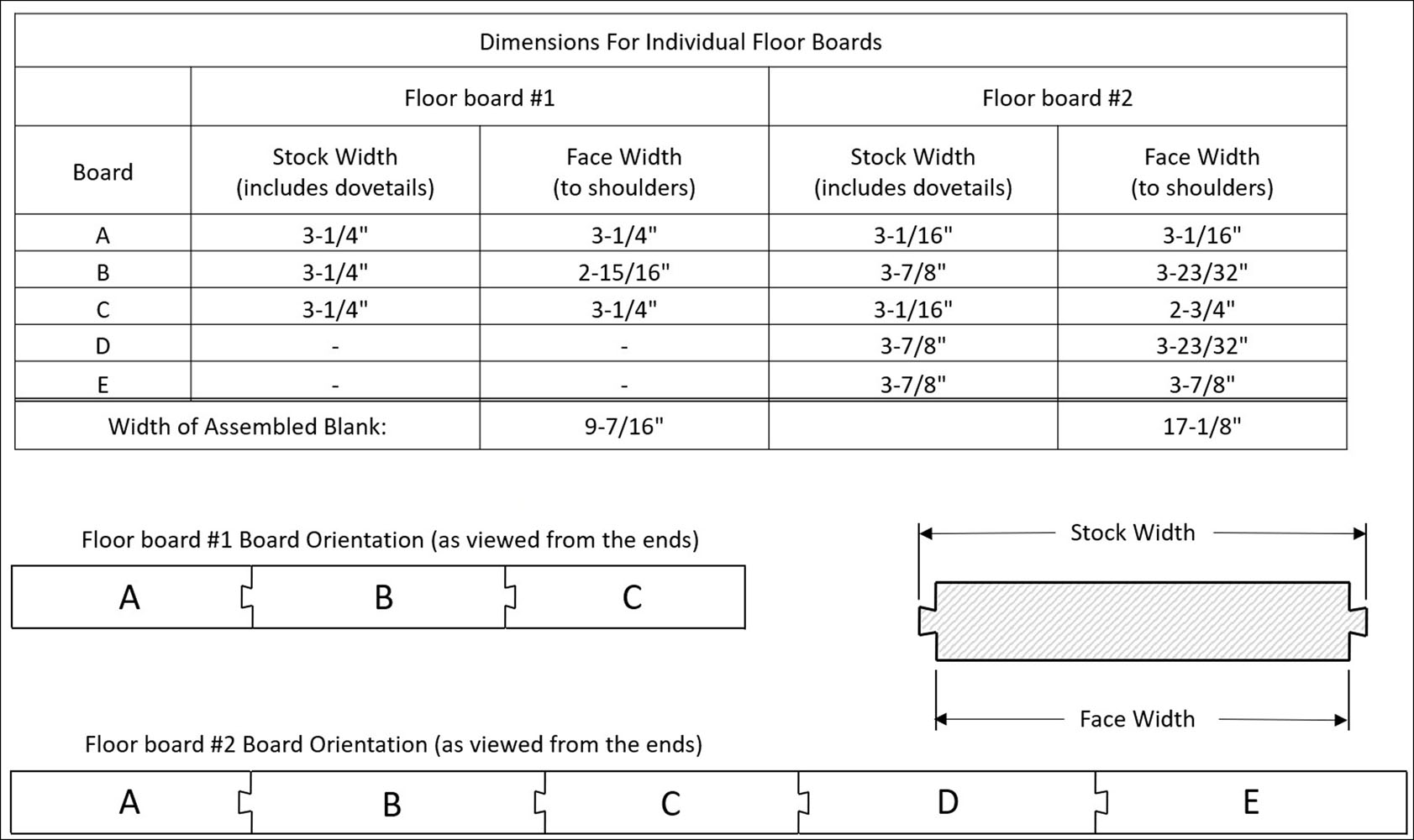
The hardwood that I used was soft maple, which is strong and has a closed grain with a smooth, even texture. Floor board #1 (angled floor board inside the cowl) was made from 3 boards and floor board #2 (horizontal floor board in front of seat) from 5 boards. Ford drawings do not specify the number or width of the individual boards, other than to “Make up from Linderman stock”. The drawing also states the stock boards are to be “in widths of 3 inches and over” before cutting the dovetails. Board widths would have been random when using the Linderman machine.
Figure 2 shows the two floor board cross sections, with the suggested number of boards and widths. The widths were chosen to resemble original floor boards but can be adjusted to best fit your needs. Also shown are the dovetail orientations with the center board having a dovetail on two edges. While not required, this orientation has been observed on original floor boards and most likely depended on operation of the Linderman machine.
Once glued up, the overall size of the rough blank is the sum of the board face widths and should be slightly larger than the final floor board to allow for cutting of the perimeter shape.
The example board widths were chosen to provide 1/4 inch of excess material after assembly. Note that the length of the boards must also be greater than the final width of the floor board.
In order to ensure that your finished floor boards are good fitting and flat, all individual boards should be planed to the final thickness of 11/16 inches and jointed for straight, square edges prior to dovetailing. This is very important as otherwise you may find dovetails that are too large or small, or grooves that are off center.
Your planed and jointed boards should now be ready for the dovetails.
Cutting The Dovetails
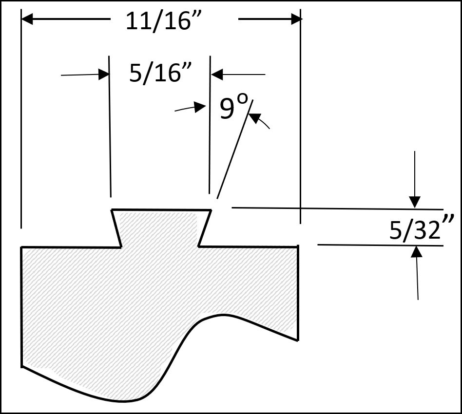
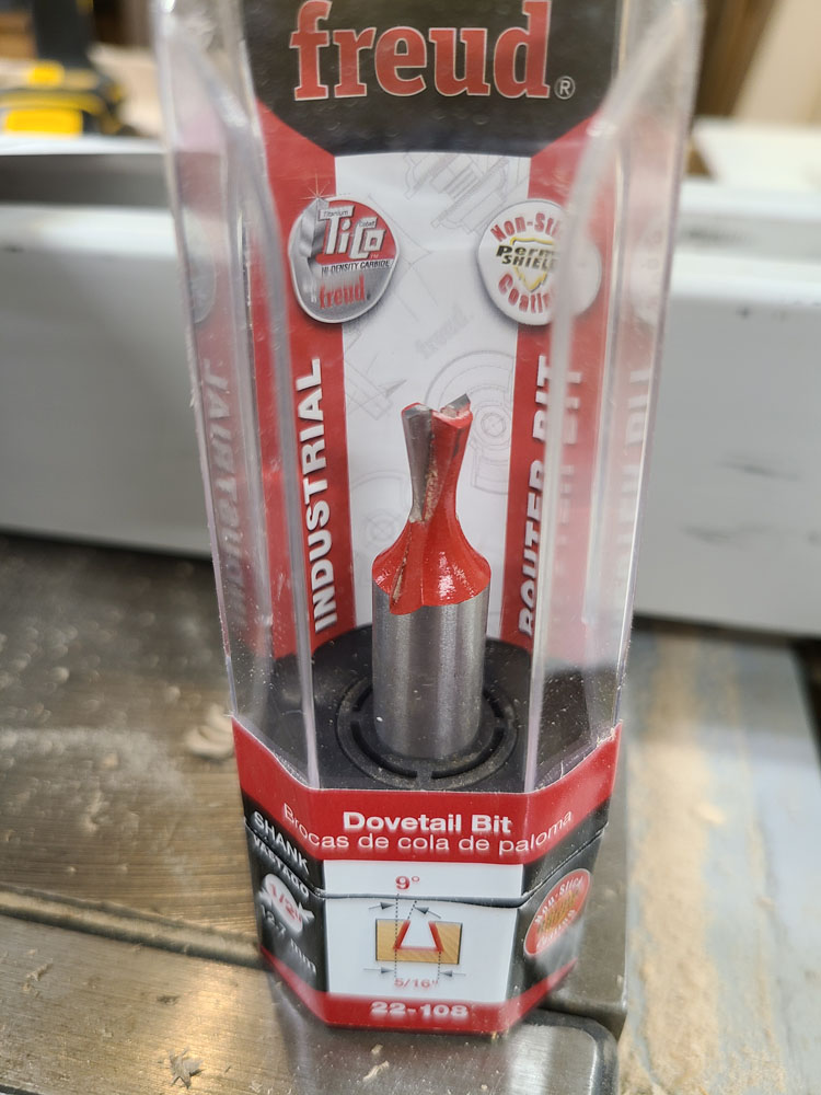
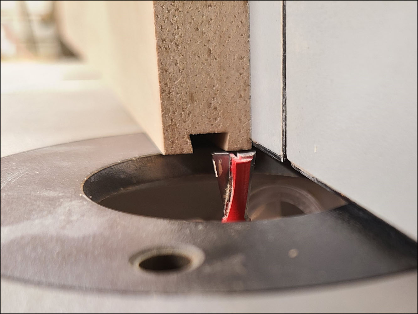
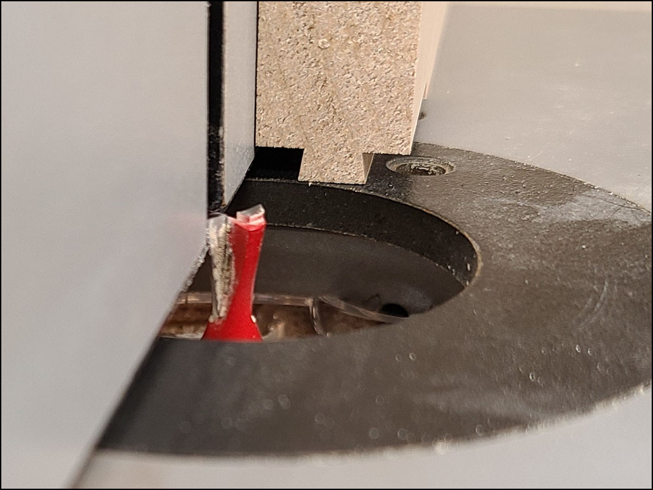
The dovetail dimensions shown in Figure 3 are based off measurements from original floor boards. I used a 5/16 inch, 9 degree dovetail bit with 1/2 inch shank as shown in Figure 4. The router was mounted underneath a router table with fence. Figure 5 and Figure 6 show the dovetail set-ups for the tails and grooves.
The groove is made in a single pass and needs to be accurately centered in the edge of the board. The dovetail requires two passes, one on each side of the board/tail.
Use a calipers to help adjust the set-up until the grooves and dovetails are centered and slide together easily. Run some tests with sample boards before making the final cuts.
If the dovetails are too loose, you risk losing strength. If the dovetails fit too tight, they can be difficult to assemble and there is an increased chance of breaking off the tail during assembly.
Assembly
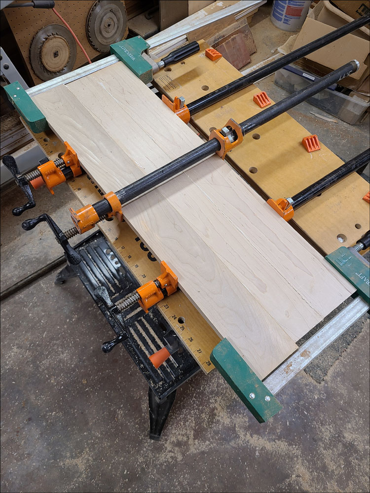
To assemble the floor boards, brush a quality waterproof glue on the dovetailed edges. Slide the boards together and clamp as shown in Figure 7, making sure they are clamped evenly to hold the boards flat. Alternate the clamps on each side of the boards and don’t over tighten. Let them dry until the glue is set.
At this point, there may need to be some leveling of the boards/joints, however don’t overdo. Original floor boards were mass produced and covered by a mat or carpet, so not much effort was made to create a fine surface.
At this point, the floor board profile can be laid out on the blank. Dimensions can be referenced on drawings or even measured from original floor boards.
Measurements should be validated relative to your actual cab as much as possible, including the location of the transmission tower and other controls.
Perimeter Fit Up
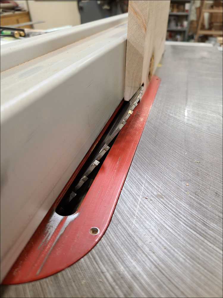
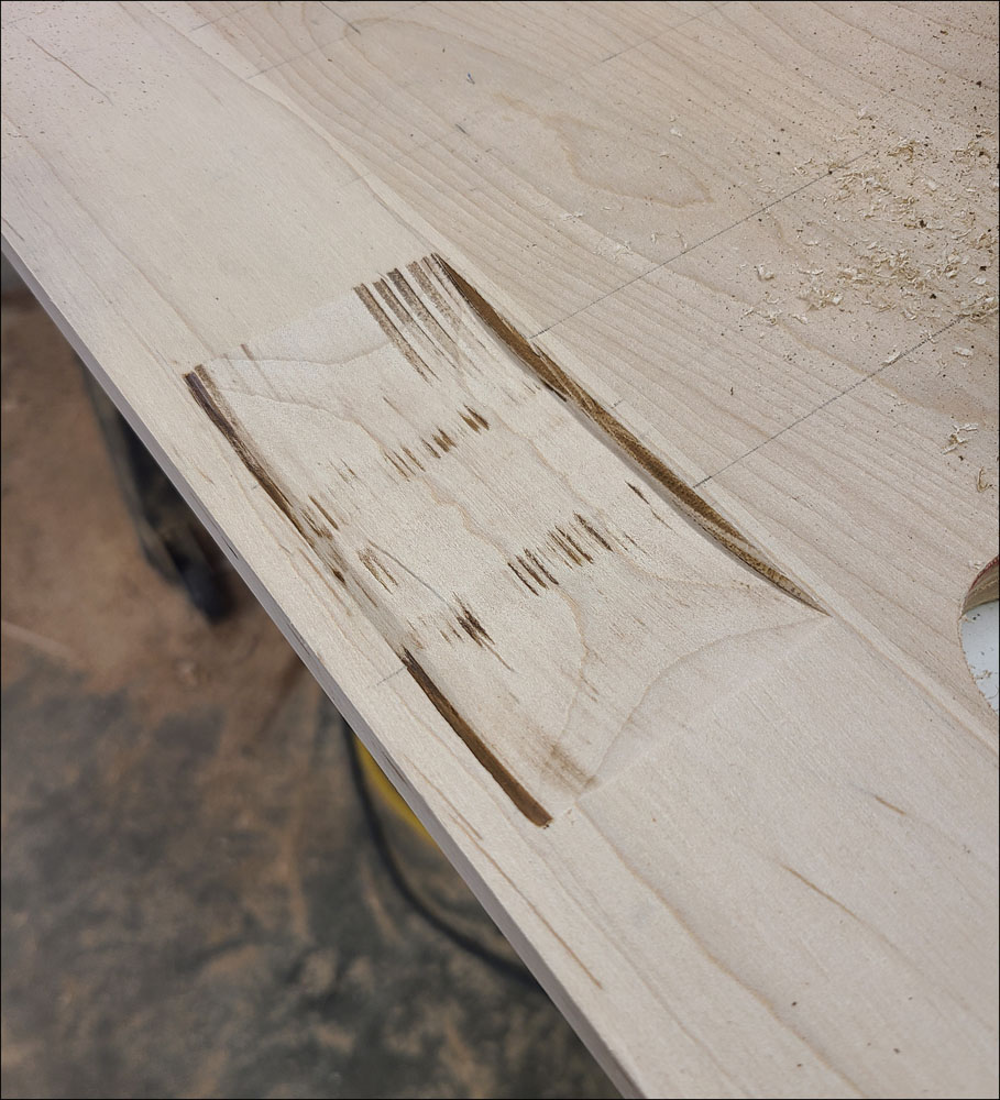
Now the floor board perimeter can be cut, including the beveled edges between the two floor boards. Figure 8 shows a representation of the beveled edge being cut on the table saw, with guards removed for visibility.
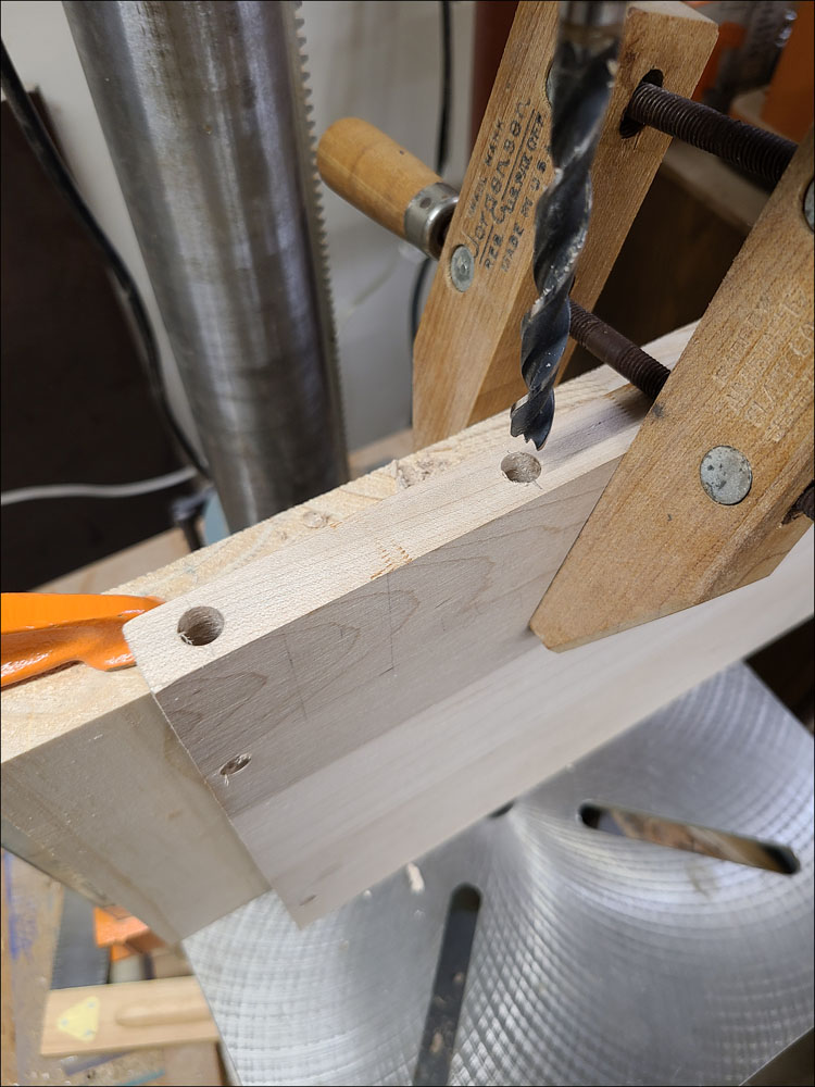
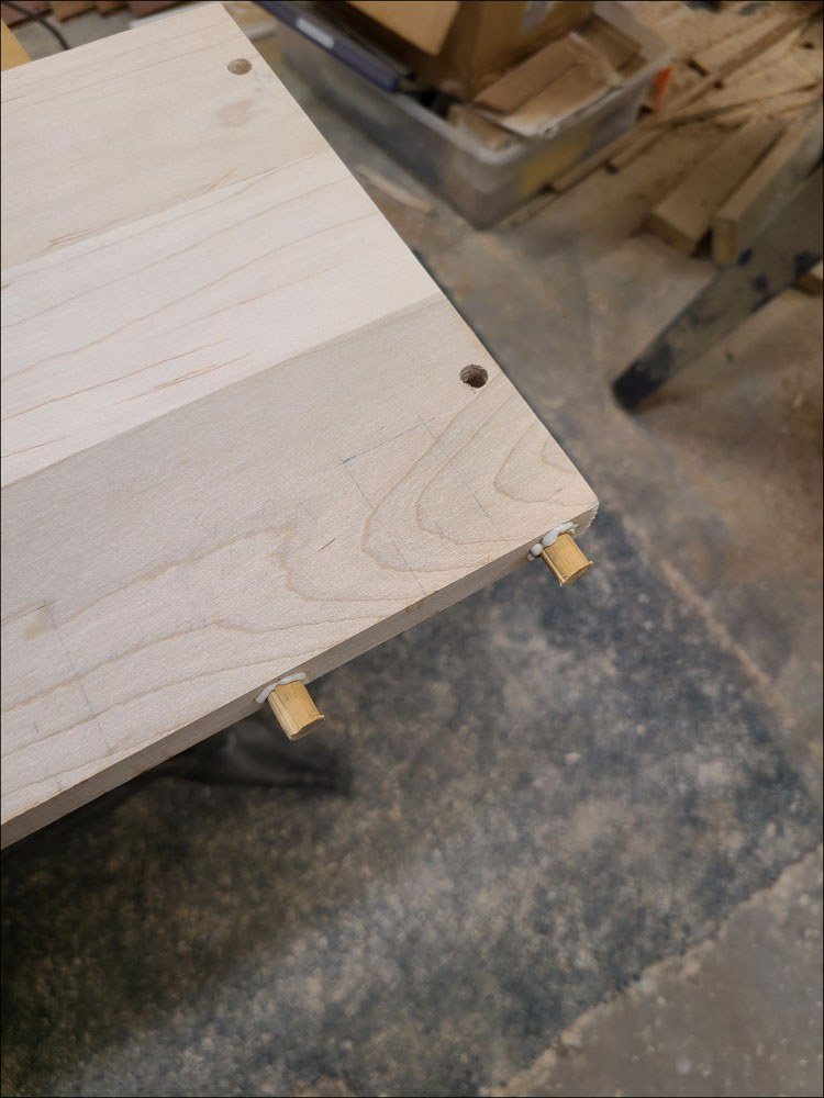
Before cutting the slots for the brake and clutch pedals, strengthen this area with reinforcement dowels inserted from the edge. Drill the holes for the dowels using a brad point drill bit as shown in Figure 9. The use of a drill press will help ensure the hole is straight into the center of the board. Make the dowels with a little extra length and groove them lengthwise to allow excess glue to escape during assembly. Glue the dowels and tap in with a hammer as shown in Figure 10. Once dry, trim the dowels flush with the edge of the board.
Once the perimeter of the floor board is cut, the boards should be trial fit within the cab floor to determine if any adjustments are needed.
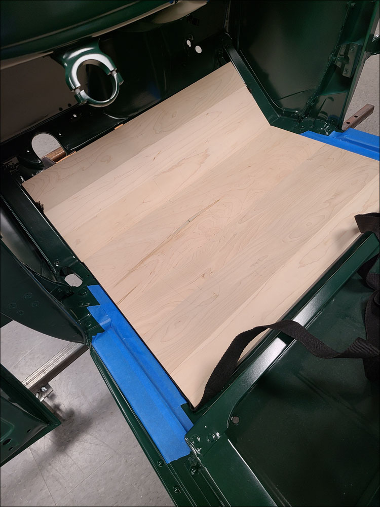
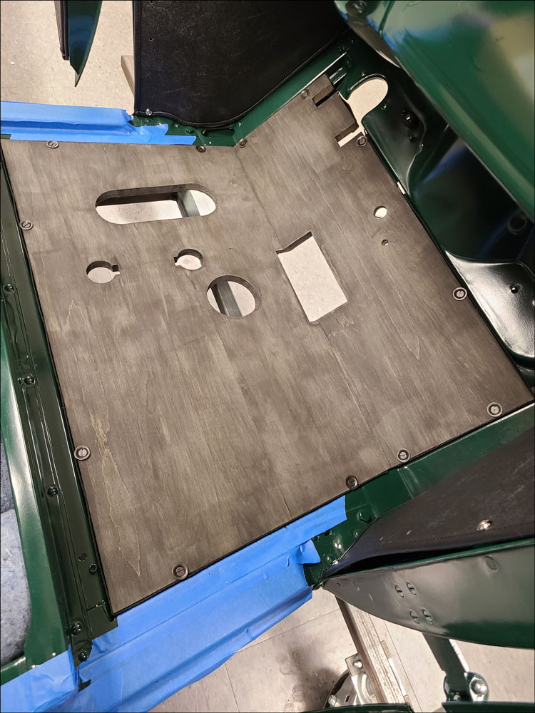
If your cab is on the truck, you will need to cut the clearance holes for any controls that are present, such as accelerator, transmission, and dual-high pedal. If the cab is off the truck as shown in Figure 11, the clearance holes may be cut later, once the perimeter is finalized.
The perimeter fit should be made with floor board welting inserted to ensure that edge clearance is correct. It is not unusual to need trimming of the profile to get a good fit up with the cab, as the cab floor can be out of square or size.
Floor board #2 is reinforced underneath with steel floor board straps (cleats) and beginning in early 1928 they were changed to overlap with floor board #1.
These straps should be trial fit at this time as they will help maintain position between the two floor boards. Straps were either fastened with screws (early) or tubular rivets (later).
After positioning the straps, drill pilot holes for the screws, or through-holes for the rivets. Temporarily fasten the straps with screws and remove once fit up is complete.
Once the perimeter is finished, the floor board mounting screw holes should be located since they will position the floor boards within the floor sills. Again insert the welting but don’t cut it yet, just using it in enough places to locate the boards as shown in Figure 11.
Mark the hole locations by inserting a center punch from the bottom and through the cab rail D-nuts. The front holes on floor board #1 and the rear holes on floor board #2 should be marked first. To properly locate the boards fore/aft, adjust the marks to achieve a 5/16” distance from the edge of the board.
Drill the front and rear holes and re-install with the welting and screws. Ensure a good fit between #1 and #2 floor boards and use the angled reinforcement straps to support both boards.
Mark locations of the remaining screws along the sides of each floor board and drill. This is a good time to final fit the floor boards with all the mounting screws and washers. All the mounting screw holes need to be countersunk from the top to fit the special floor board washers.
Creating Features
Once the floor board mounting holes are complete, the necessary features can be created.
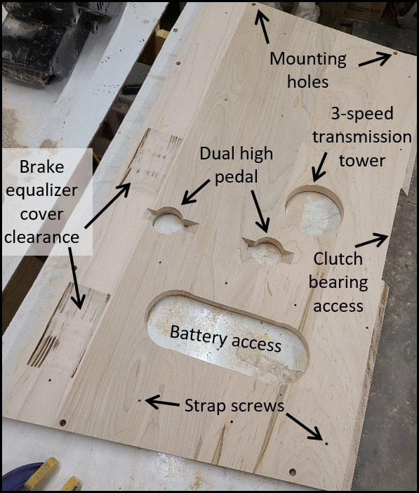
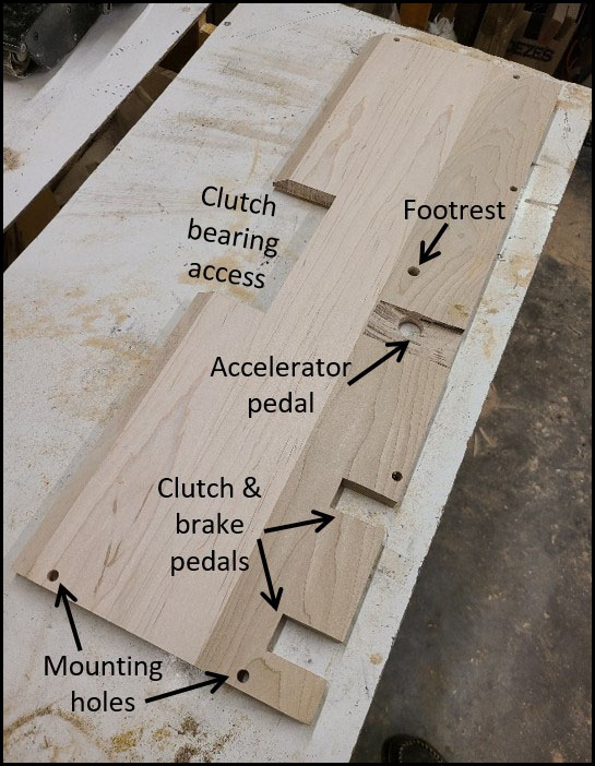
The floor boards in this article were for an early truck equipped with left-side hand brake. It has brake equalizer pin covers, dual-high auxiliary transmission pedal, accelerator pedal, transmission tower, and clutch access cover.
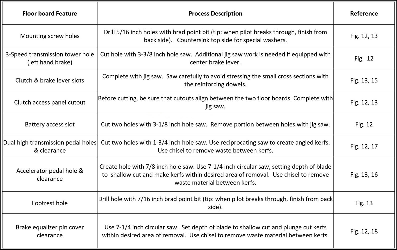
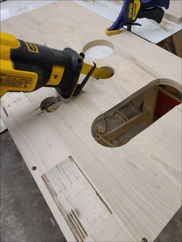
I used a combination of hole saws, drills, jig saw, circular saw and reciprocating saw to create the required features as identified in Figures 12 and Figure 13 (shown from the bottom side).
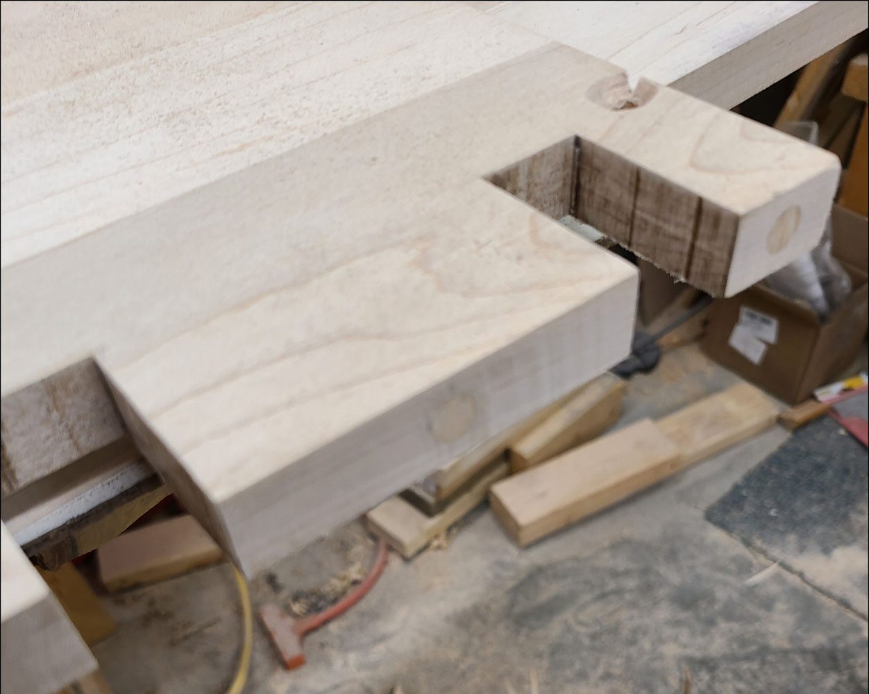
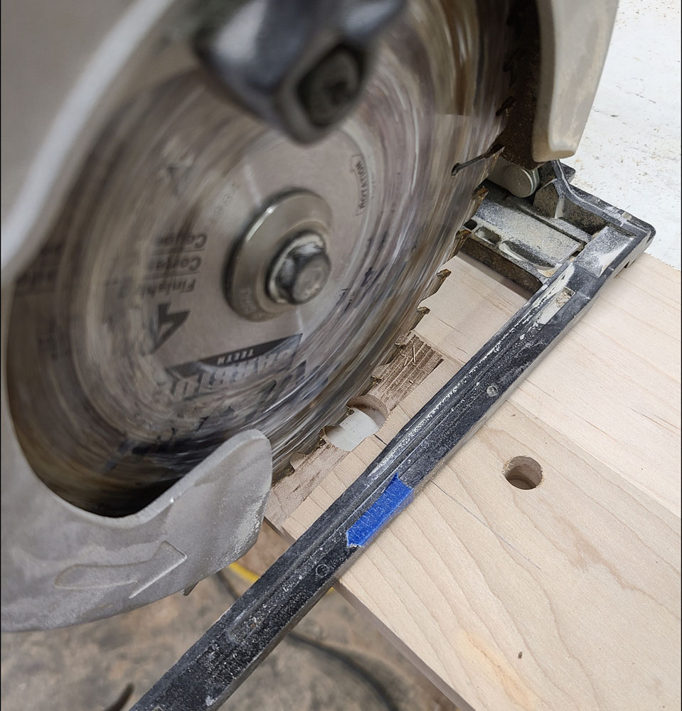
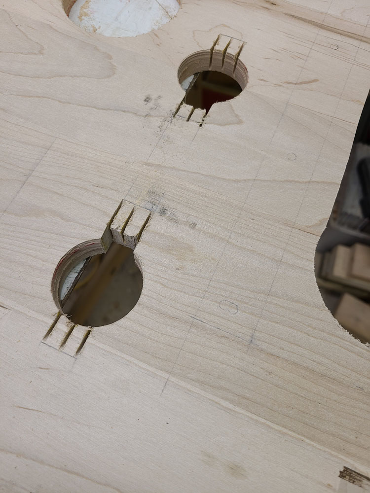
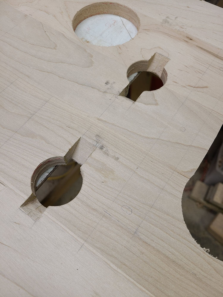
Figure 14 summarizes the processes to create the features, along with references. Review Figures 15—18 for additional details of the features for clutch/brake slots, accelerator pedal, dual high pedal, and brake equalizer cover.
Finish and Welting
Once the floor boards are complete the finish can be applied. Original floor boards were dipped in a dull black wood preservative. I brushed on a couple coats of CreoCoat Black Wood Preservative by Woodlife.
Lastly, the welting can be cut to fit around the perimeter. There is no welting between the two floor boards. The edge of the board is covered with welting, with the top edge of the welting flush with the top surface. The remaining width of welting is wrapped underneath the boards.
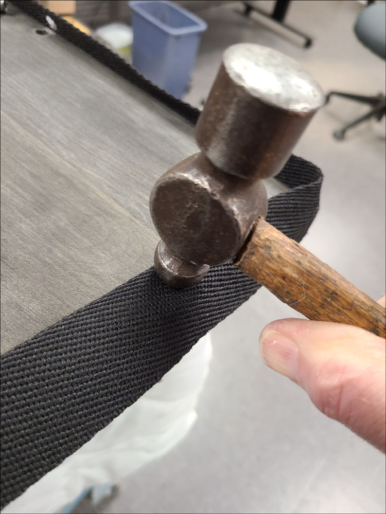
Use the round end of a small ball peen hammer to press an indentation where the mounting screw holes need to be, as shown in Figure 19 and Figure 20.
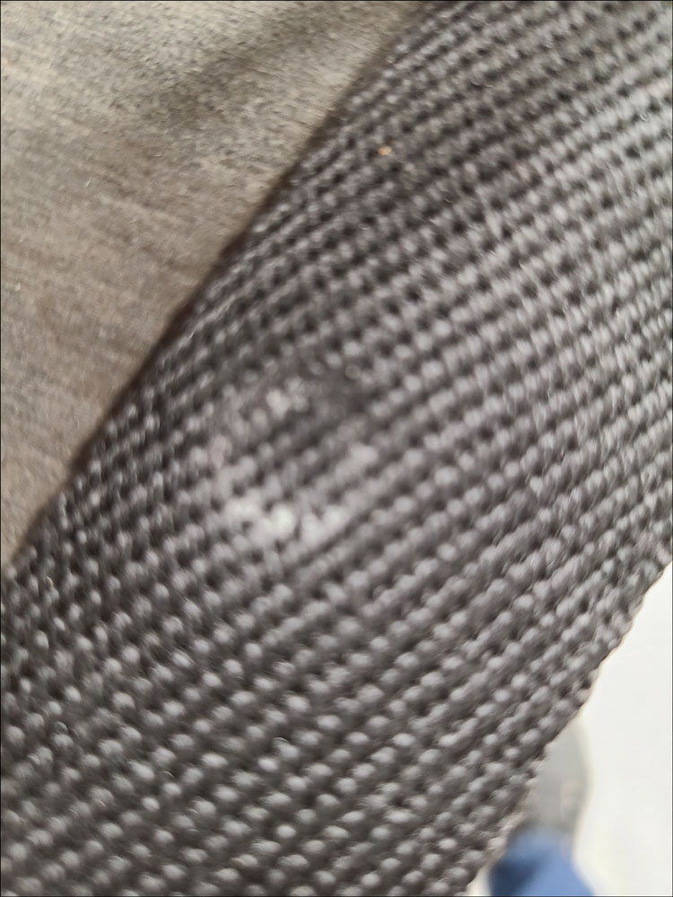
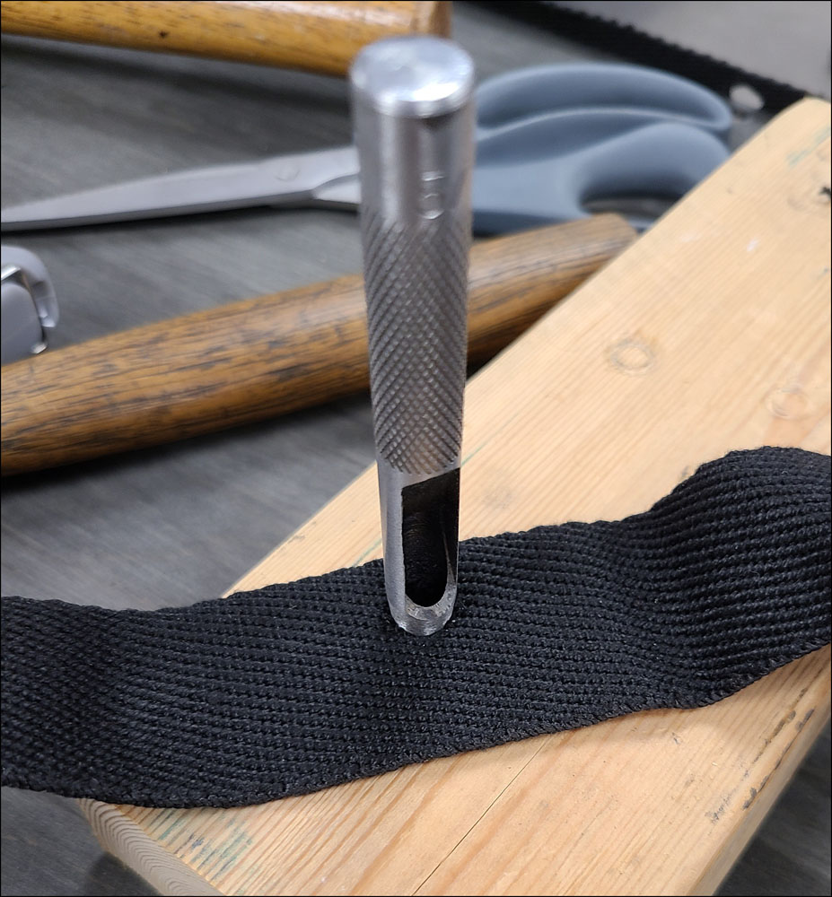
Then use a hole punch to form the hole as shown in Figure 21. The flame from a lighter may be used to lightly singe the holes and ends to prevent fraying.
The welting may then be applied to the sides and wrapped underneath, trimming where necessary and tacking with a minimum number of upholstery tacks to hold in place. Use extra caution when tacking around the clutch and brake slots to not break the small sections with the dowels.
Summary
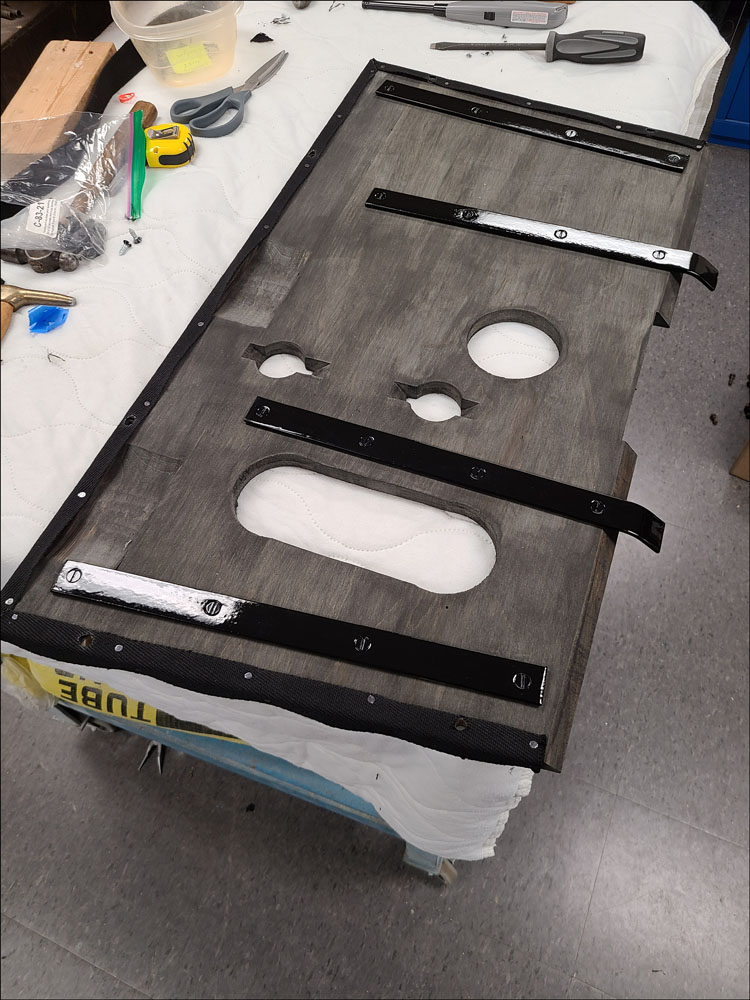
Figure 22 shows the underneath of completed floor board #2 and Figure 23 shows both completed floor boards assembled into the cab.
List of Tools Used:
- Table Saw
- Planer*
- Joiner*
- Drill Press*
- Router and table with fence*
- 5/16″ x 9° dovetail router bit*
- Handheld Drill
- Brad-point fluted drill bits (5/16”, 3/8”, 7/16”)
- 76° countersink bit (3/4” diameter recommended)
- Hole saws (diameters 7/8”, 1-3/4”, 3-1/8”, 3-3/8”)
- 7-1/4” Circular saw with wood cutting blade
- Reciprocating saw with wood cutting blade
- Jig saw with wood cutting blade
- Chisels (1/4”-1/2”)
- Ball peen hammer
- Tape measure
- Digital calipers
- Square
- Clamps
- Upholstery hammer
- 5/16” hole punch
- Center punch
*required only for hardwood floor boards
List of Materials Used:
- Soft maple boards (11/16” final thickness)
- Waterproof wood glue
- Wood dowels (3/8”)
- Steel reinforcement straps & screws or tubular rivets
- Floor board screws and special washers
- Black wood preservative
- Floor Board welting (approx. 1-1/2” wide)
- Upholstery tacks
References:
- Model “A” Ford Judging Standards & Restoration Guidelines (by MARC & MAFCA) 2016 revision
- AAFords-FMAATC @ https://aafords.com/ (follow: Body Types/Index-Body-Details/Floor Boards)
- The Double A’er Newsletter, https://aafords.com/c/nl/#ta (AA Truck Talk articles on floor boards by Neil Wilson: Issue 13, April 2007 -Floor Boards & Mats; Issue 28, April 2022 -Floor Boards)
- “1909 Ad-Linderman Machine Co. Dovetail Glue Jointer.” Wood Craft, Sept. 1909