
2024/12/04 update
Page Contents
*******TOC Dropdown – Tap/Click*******
Overview
This article covers #1 (slant) and #2 (flat) floor board designs used for USA production AA-vehicles.
Note – For this article, the names “#1fb or #2fb“, “#1fb or #2fb assy-cmpl”, and “floor board #1 or #2 assy-cmpl” are used for identification.
These names refer to complete assemblies including sub-assemblies/parts such as the bare floor board assemblies, board cleats, and board weatherstrip/anti-squeak.
Abbreviation RGJS = Restoration Guidelines and Judging Standards which is available from either national Model A club (MARC and MAFCA).
Production Summary
1927—Late 1929
3-Speed Transmission Equipped – AA-vehicles used the A-vehicle #1fb with its design changes (part A-35130 d1-d7).
AA-vehicles without a dual high transmission used the A-vehicle #2fb’s with their design changes (parts A-35131 d1-d2 and A-35131-B d1-d2).
For AA-vehicles equipped with a dual high transmission, AA-82160 d1-d2 and AA-82160-B d1-d2 #2fb’s were used. These assemblies were the same as those used with the A-vehicle but had two holes for the dual high transmission shifter pedal.
Late 1929
4-Speed Transmission Equipped – The AA-chassis was fit with a four-speed transmission beginning in late 1929 (most likely September 1929). AA-vehicles for late 1929 used the A-vehicle #1fb A-35130 d7 and AA-82160-C d1 #2fb.
1930—1932
Heavy-Duty AA Brake Pedal Equipped – Starting January 1930, the AA-chassis was equipped with a heavy-duty brake pedal as well as a 4-speed transmission. These AA-vehicles used #1fb AA-35130 d1-d2 (except the 315-A Standrive). This board was the same as the A-vehicle board except for a relief (grove) on the bottom (back) side that provided clearance for heavy-duty brake pedal AA-2455. Without the relief, the brake pedal hit the floor board in the released position.
For this time-period, the AA-vehicles used #2fb AA-82160-C d1–d2 (except the 315-A Standrive and 330-A/B Buses).
Drawings
Best to use a 19″ or larger monitor for viewing drawings (larger is better).
High resolution drawing images (.jpg files) are available to fmaatc members. Email Neil for a download link (sorry, no phone).
You can download the images below as wanted. However, the .jpg file downloaded will be low resolution.
Drawings Sub-Sections
#1fb Drawings – Sub-Section Contents
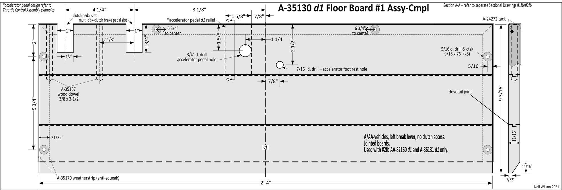
d1 – Production start. A/AA-vehicles with left break lever, no clutch access, slot location for multi-disk-clutch-brake pedal, relief for accelerator pedal d1, accelerator pedal hole dia. 3/4″. Jointed boards. Used with AA-82160 d1 & A-35131 d1 #2fb’s only.
Link – Sectional Drawing A-A
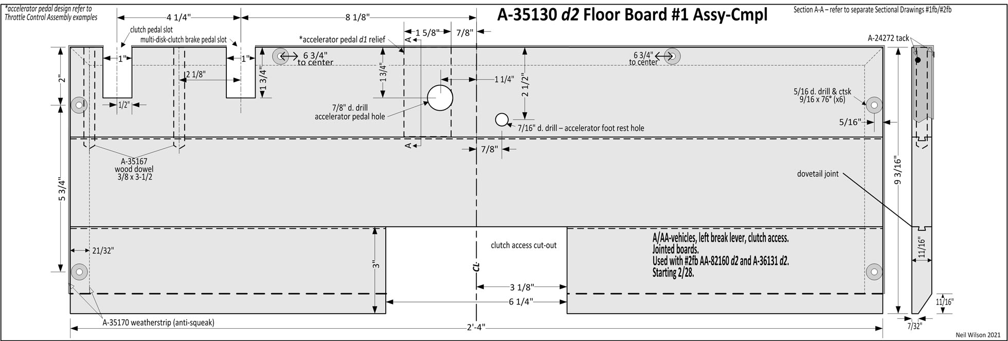
d2 – Starting 2/28. A/AA-vehicles, clutch access, slot location for multi-disk-clutch-brake-pedal, relief for accelerator pedal d1 , accelerator pedal hole dia. 7/8″ and lowered 1/8”. Jointed boards. Used with AA-82160 d2 & A-35131 d2 #2fb’s.
Link – Sectional Drawing A-A
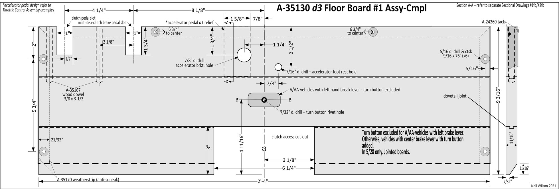
d3 – In 5/28 only. Turn button excluded for A/AA-vehicles with left brake lever. Otherwise, vehicles with center brake lever, relief for accelerator pedal d1, multi-disk-clutch-brake-pedal slot, turn button added.
Link – Sectional Drawing A-A B-B
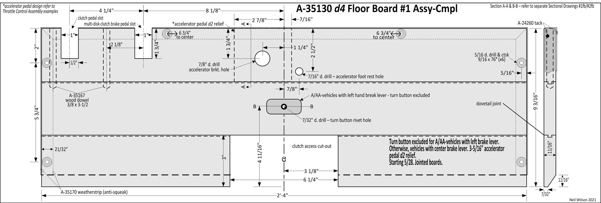
d4 – Starting 5/28. Turn button excluded for A/AA-vehicles with left brake lever. Otherwise, vehicles with center brake lever, relief for accelerator pedal d2, multi-disk-clutch-brake-pedal slot, turn button included.
Link – Sectional Drawing A-A B-B
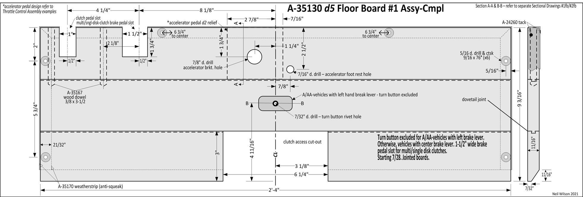
d5 – Starting 7/28. Turn button excluded for A/AA-vehicles with left brake lever. Otherwise, vehicles with center brake lever, relief for accelerator pedal d2, multi/single-disk-clutch-brake-pedal slot, turn button included.
Link – Sectional Drawing A-A B-B
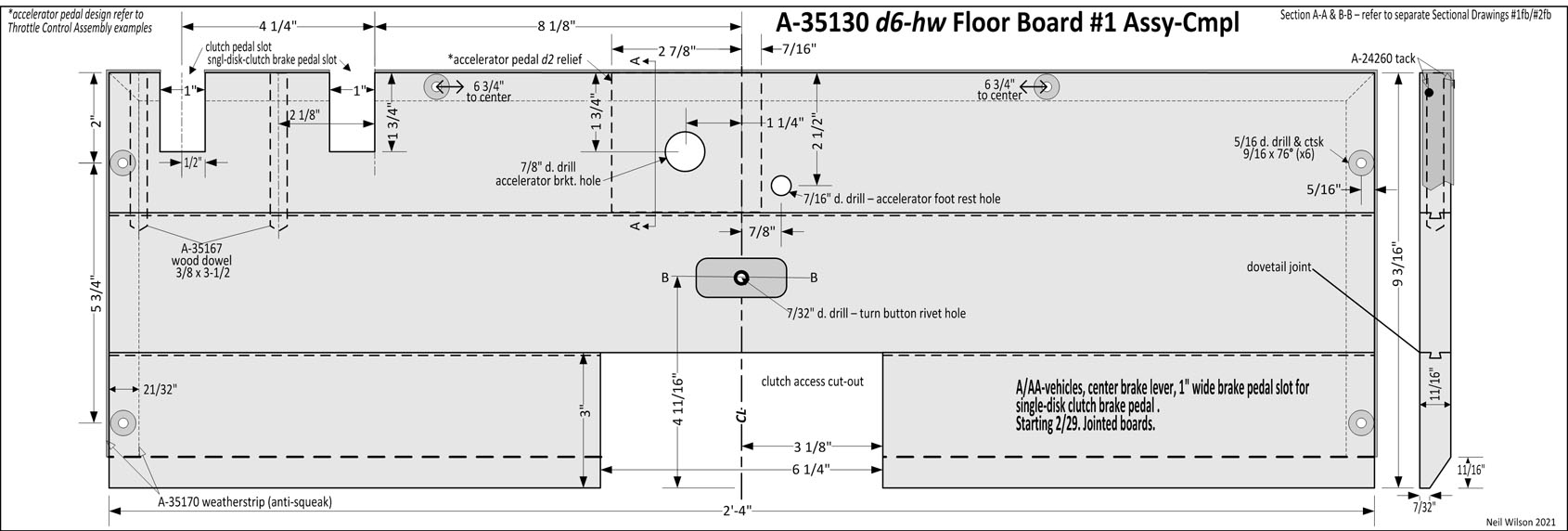
d6-hw – Starting 2/29 with hardwood jointed boards. A/AA-vehicles, accelerator pedal d2, brake pedal slot changed to 1” wide and moved for single-disk-clutch-brake pedal.
Link – Sectional Drawing A-A B-B
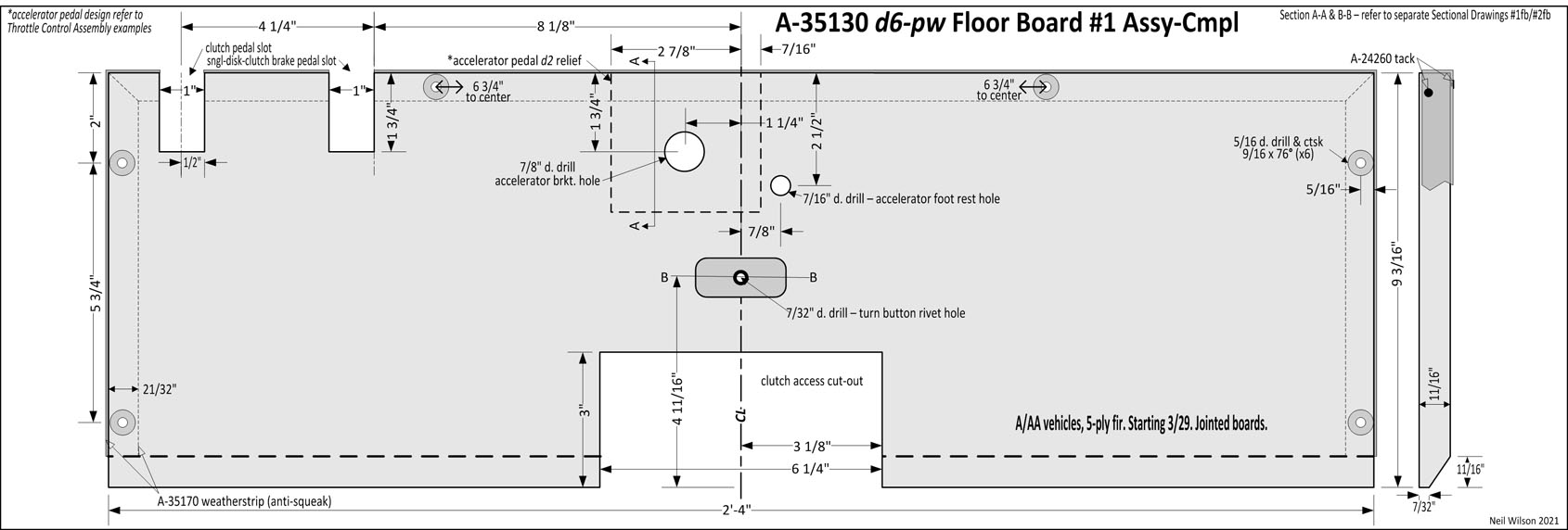
d6-pw – Starting 3/29 with plywood 5-ply fir. A/AA-vehicles, accelerator pedal d2, brake pedal slot 1” wide for single-disk-clutch-brake pedal.
Link – Sectional Drawing A-A B-B
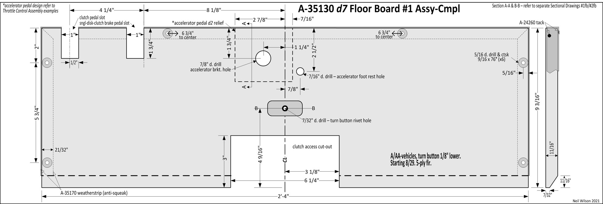
d7 – Starting 8/29. A/AA-vehicles, accelerator pedal d2, turn button 1/8″ lower.
Link – Sectional Drawing A-A B-B
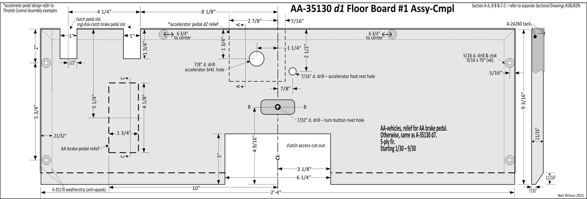
d1 – Starting 1/30—9/30. AA-vehicles, relief for AA brake pedal, accelerator pedal d2. Otherwise, same as A-35130 d7. 5-ply fir.
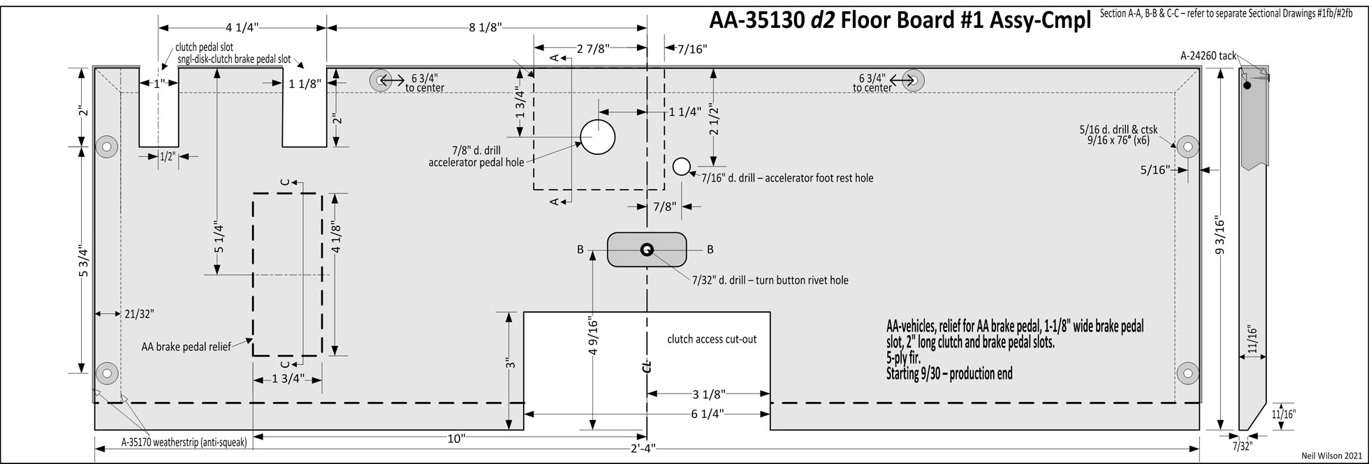
d2 – Starting 9/30 – production end. AA-vehicles, relief for AA brake pedal, accelerator pedal d2 , 2” long clutch and brake pedal slots, 1-1/8″ wide brake pedal slot. 5-ply fir.
Link – Sectional Drawing A-A B-B C-C
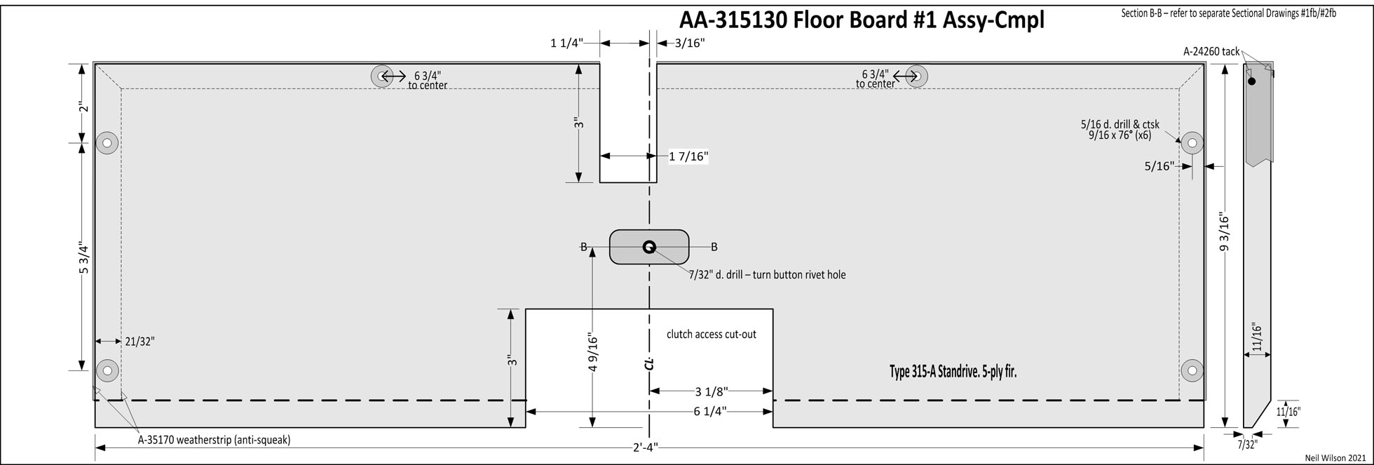
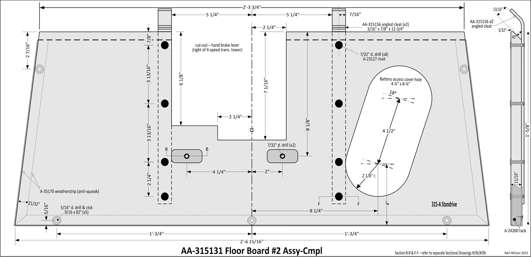
Type 315-A – Standrive production start – production end. 5-ply fir.
Link – Sectional Drawing B-B
#2fb Drawings – Sub-Section Contents
Each AA-82160 drawing includes A-35131; each AA-82160-B drawing includes A-35131-B; each AA-82160-C drawing is standalone for the AA-vehicles.
AA-315131 was for type 315-A Standrive. AA-330131 #2fb was for types 300-A/B (School/Passenger Bus).
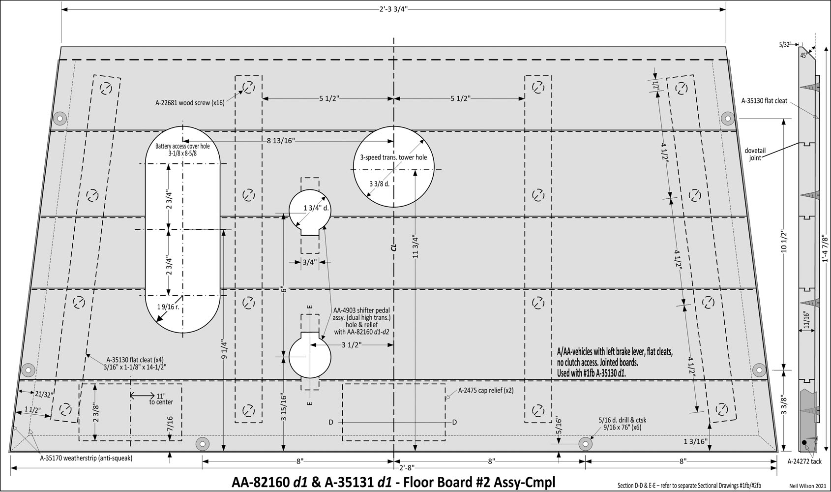
d1 – Production start. A/AA-vehicles with left brake lever, no clutch access, four flat cleats. Dual high transmission shifter pedal hole with AA-82160 only. Used with #1fb A-35130 d1 only. Jointed boards.
Link – Sectional Drawing D-D E-E
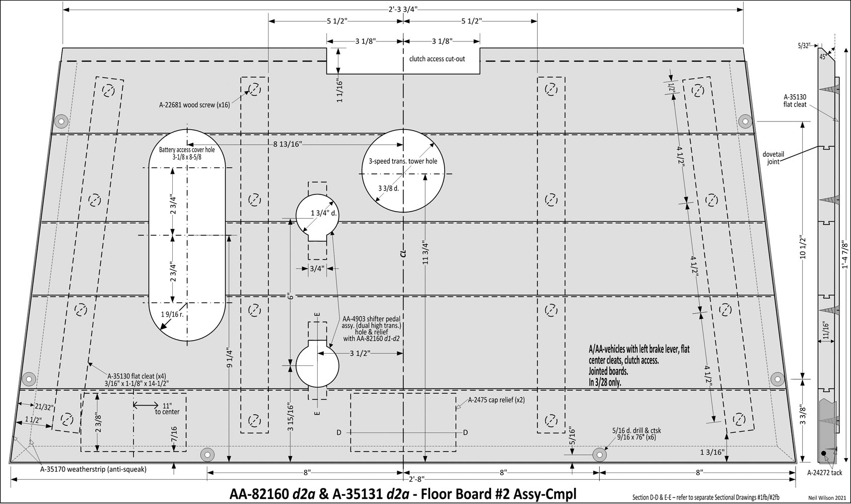
d2a – In 3/28 only. A/AA-vehicles with left brake lever, clutch access, four flat cleats. Used with #1fb A-35130 d2.
Link – Sectional Drawing D-D E-E
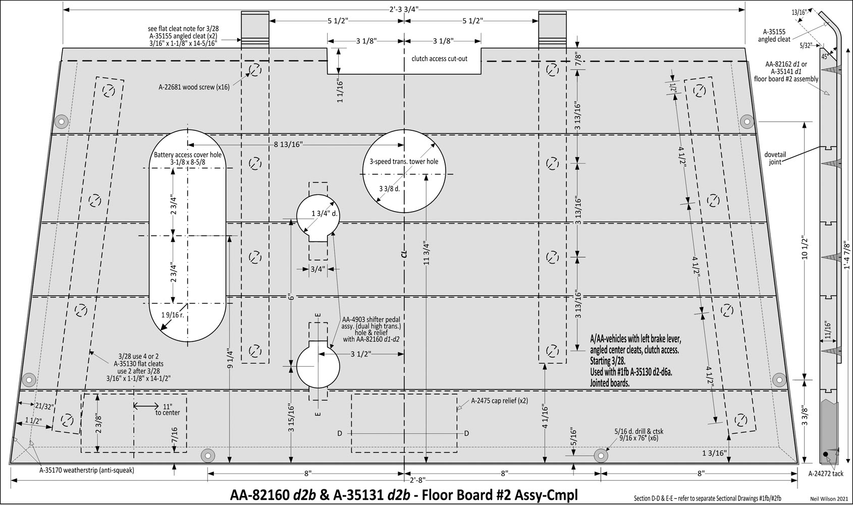
d2b – Starting 3/28. A/AA-vehicles with left brake lever, clutch access, angled center cleats. Used with #1fb A-35130 d2-d6a.
Link – Sectional Drawing D-D E-E
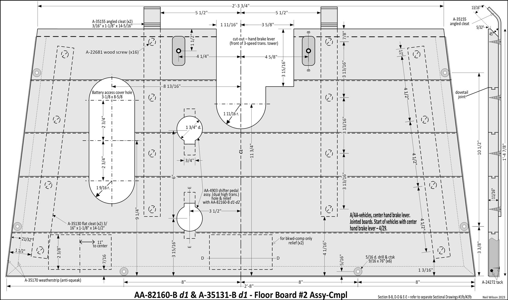
d1 – (start of vehicles with center brake lever)—4/29. A/AA-vehicles, center brake lever cutout. Jointed boards.
Link – Sectional Drawing B-B D-D E-E
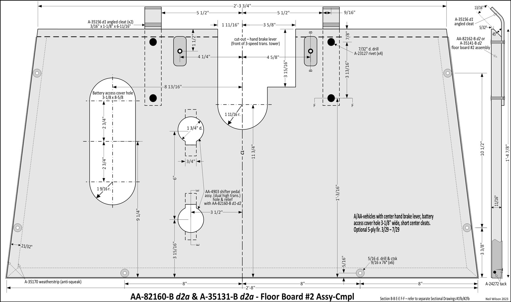
d2a – 3/29—7/29. A/AA-vehicles with center brake lever, battery access cover hole 3-1/8″ wide, short center cleats. Optional 5-ply fir.
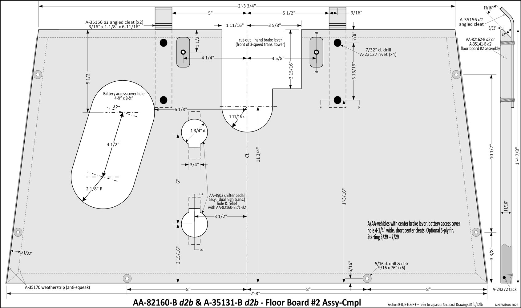
d2b – 3/29—7/29. A/AA-vehicles, battery access cover hole 4-1/4″ wide, short center cleats. Optional 5-ply fir.
Link – Sectional Drawing D-D E-E F-F
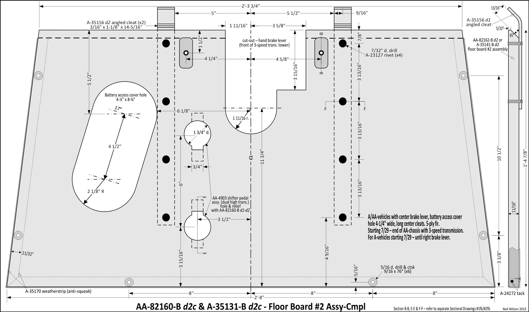
d2c – 7/29—(end AA-chassis with A-chassis 3-speed transmission). A/AA-vehicles, long center cleats. 5-ply fir. For A-vehicles 7/29 – until right brake lever introduced.

d1 – Start of vehicles with 4-speed transmission (likely 9/29). AA-vehicles, right brake lever on 4-speed transmission, two turn buttons, long rivet-on angle center cleats. 5-ply fir. With types 76-A, 82-A, 85-A.
Link – Sectional Drawing B-B F-F
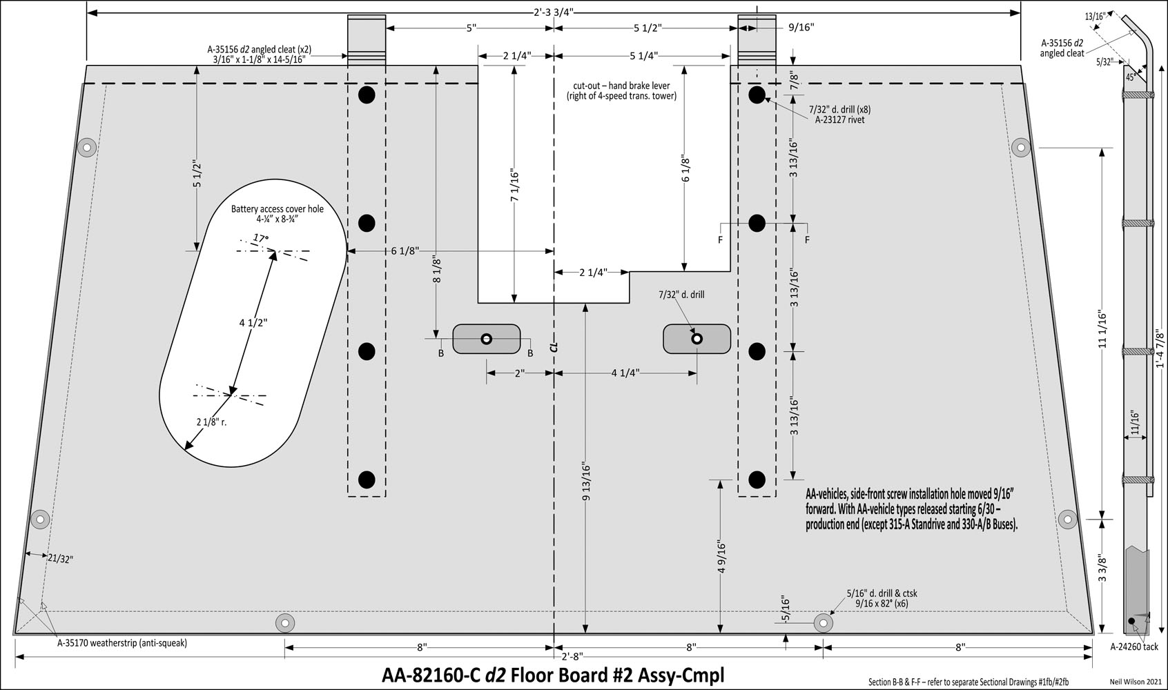
d2 – With AA-vehicle types released starting 6/30—1932. AA-vehicles, side-front screw installation hole moved 9/16” forward. Excludes 315-A Standrive and 330-A/B Buses.
Link – Sectional Drawing B-B F-F
AA-330131 Floor Board #2 Assy-Comp – No Ford drawing found yet.
Type 330-A/B – Bus (school/passenger).
Sectional Drawings – Sub-Section
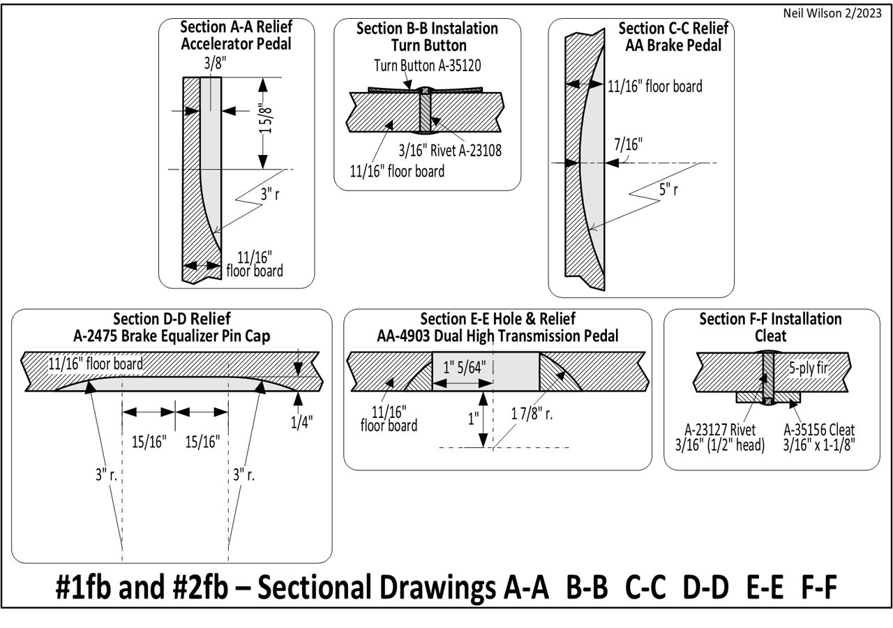
The preceding individual floor board drawings have notations indicating cross-section drawings (e.g. A-A, B-B, etc.).
The image below provides the sectional drawings of the six cross-section notations on all #1fb’s and #2fb’s drawings.
Board Materials & Finish
Board Material
Per the RGJS, dovetailed hardwood boards (i.e. jointed boards) were used for floor boards through 1929. Plywood was used starting March 1929 and replaced jointed boards soon after. Few (if any) hardwood boards were actually produced from May 1929 forward based on observations over the years.
Note – Per Ford drawings, 5-ply fir was added to the material list 10/17/28. All Ford drawings (after 3/29) show both hardwood boards and plywood could have been used.
Ford drawings, list of board materials was – from Linderman stock in 3” widths or over – Maple-Beech-Birch-Elm-Oak, or 5-ply fir. In 2/30 optional “Dense Southern Yellow Pine” was added and an optional “V” grove joint was added.
Board Finish
Boards were treated with a dull black wood preservative per the RGJS. In January 1930, “To be painted with M-1208-B” was added to drawings. This was likely specified in Ford’s wood specifications prior to 1/30. Paint should be applied to the machined floor boards before any attachments to allow edges and holes to be covered.
Weatherstrip/Anti-Squeak
Per the RGJS, board edges (excluding the mating edges) were fitted with a brownish fabric anti-squeak (weatherstrip). It was 1 to 1-1/2 inches wide and attached with small black enameled tacks. The weatherstrip was flush to the edge-top-surface with the remainder tacked to the underside.
Note – Per Ford drawings, the weatherstrip was slightly less than flush to the edge-top-surface with 21/32” under the board. It is suggested that the weatherstrip be notched or punched at each installation screw hole. Any interference here makes board installation harder.
Linderman Stock
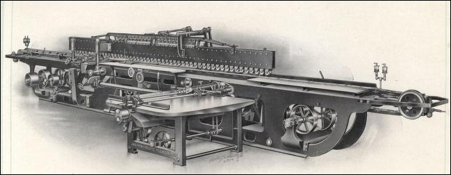
This is a reference to the Linderman Machine Co. of Muskegon, MI. Their “Automatic Dovetail Glue Jointer” was used to produce jointed boards.
Cleats – #2 Floor Boards
Ford drawings have part ids for each type of cleat (i.e. strap) attached to the bottom side of #2fb’s. These cleat parts are as listed here (definitions via observation of original parts).
Cleat installation is shown on each #2fb Drawing.
Note – Per the RGJS, cleats are referenced as steel straps (flat straps, angled straps, short angled straps) with the straps and attachment hardware being black enamel paint finish. Straps were 1-1/8” wide through 12/30 and 7/8” wide thereafter.
- A-35130 – flat cleat 3/16” x 1-1/8” x 14-1/2” attached using four A-22681 flat head slotted wood screws.
- A-35155 – angled cleat 3/16” x 1-1/8” x 14-5/16” attached using four A-22681 flat head slotted wood screws.
- A-35156 d1 – short angled cleat 3/16” x 1-1/8” x 6-11/16” attached using two A-23127 tubular rivets.
- A-35156 d2 – angled cleat 3/16” x 1-1/8” x 14-5/16” attached using four A-23127 tubular rivets.
- A-35156 d3 – angled cleat x/xx x 7/8” x x-x/xx attached using four A-23127 tubular rivets.
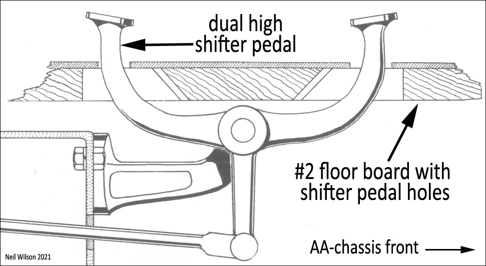
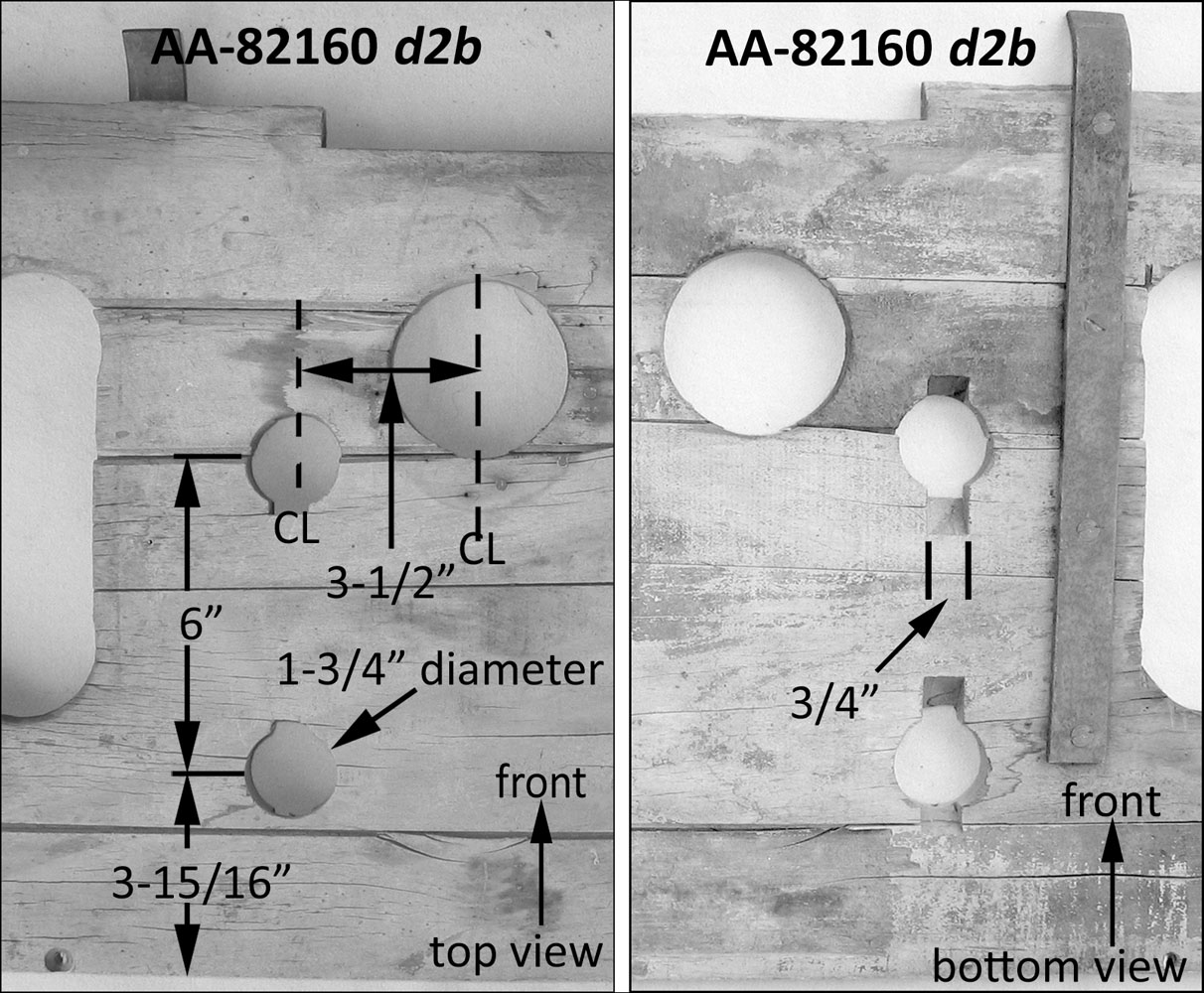
Dual High Shifter Pedal Holes – #2fb Example
The AA-82160 and AA-82160-B floor board drawings show the holes for the dual high shifter pedal as seen in the three images here.
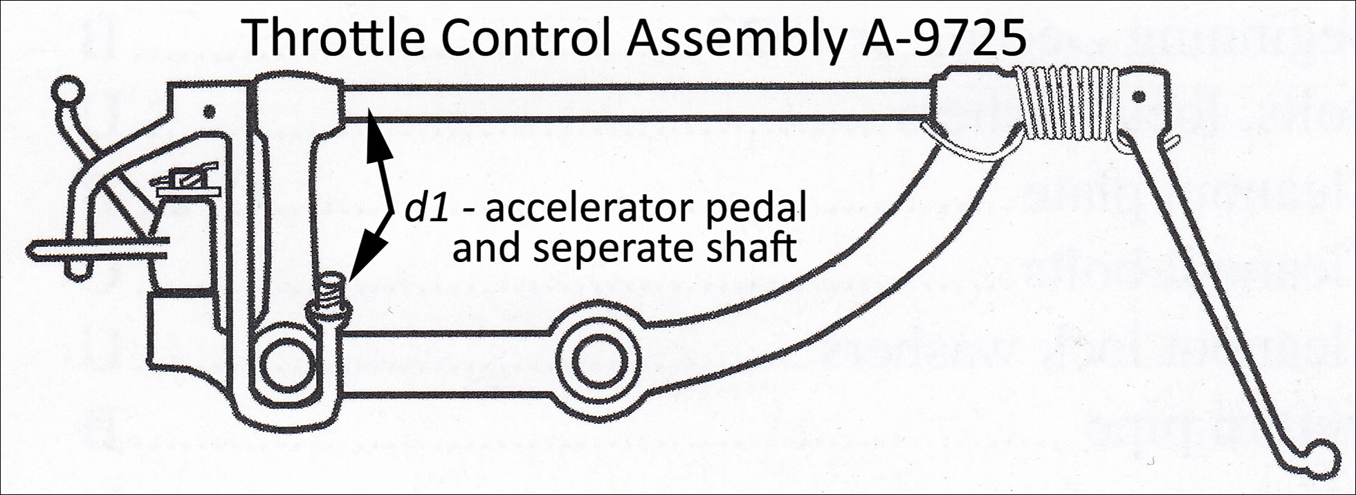
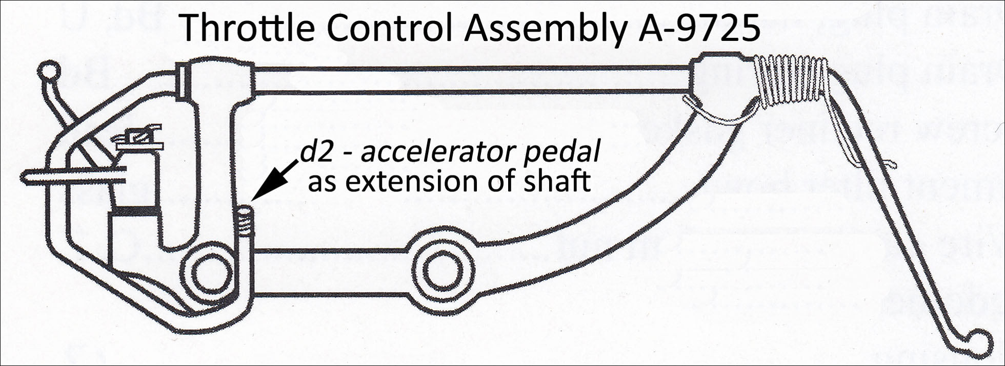
Accelerator Pedal Designs
#1fb drawings have accelerator pedal d1 and d2 notations for reliefs on the backside of the boards. The two pedal/shaft designs for the A-9725 Throttle Control Assemblies are shown below.
The 1-piece d2 pedal/shaft required a 3-5/16” wide relief. It was backwards compatible with the 1-5/8” wide relief initially used for the 2-piece d1 pedal/shaft.
Refer to page 1-17 of the RGJS for the seven throttle-control-assembly illustrations.
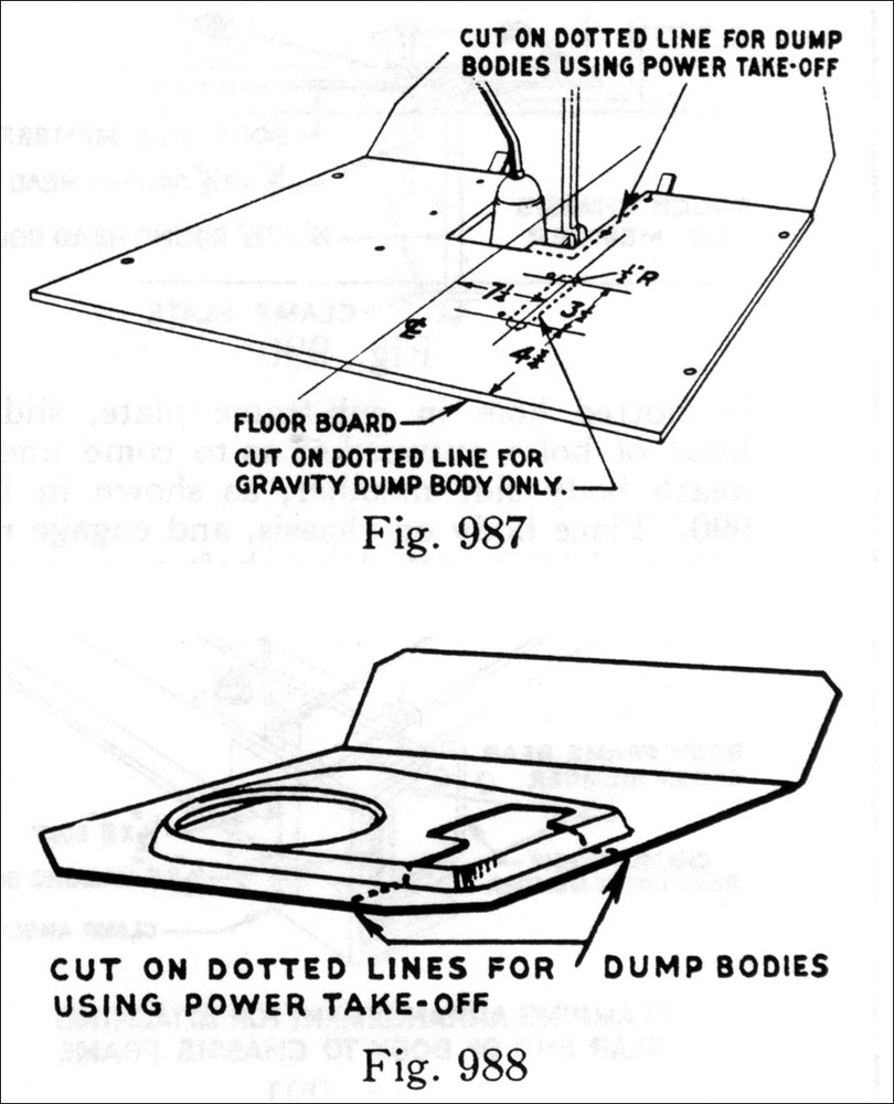
PTO Handle Clearance
In September 1930, Ford began selling complete dump trucks. Some of these units required an additional handle coming up through the floor for power take-off operation. Page 493 (9/30) of the Ford Service Bulletins has information regarding the requirement for power take-off handles.
Both the floor board and the emergency lever plate had to be cut to allow room for handles.
Plates – Seals – Weather Pads
Floor board plates, seals and weather pads are not covered in this article. Information and photos are provided in the RGJS pages 11-4—11-7 and page E-61.
Floor Board Reproduction/Considerations
Reproduction
Floor boards matching the original drawings found above on this page are not available for the most part.
Jointed-board floor boards are not being reproduced (as of 2023). Vendors sell plywood floor boards for the A/AA-bodies which are used by all but those doing assembly-line-type restoration. For those interested in originality, reproduction is up to the restorers.
An article (provided by Brian Jensen) details the milling and finishing of both #1fb and #2fb. Procedures to follow with many photographs as well as the tools required are provided. This article is at the link below:
Body Preparation
All of the d-nut threads for floor board installation should be rethreaded as needed. It is important to ensure that the d-nuts are not tilted in the body channel. Installation screws are inserted through the floor board holes and then threaded into the d-nuts. A poor alignment of the d-nuts will not allow the screws to be installed.
Each d-nut can be tested before the floor board is installed by screwing in a long screw and viewing its angle. FYI – A large crescent wrench fit over the d-nut can be used as a lever for straightening.
Body Shimming
Shimming the body to align doors can result in misalignment of the accelerator pedal and brake/clutch pedals to #1fb cut-outs.
Floor Board Fitting
It is best to fit #1fb and #2fb to the body prior to drilling installation screw holes. It has been found that there are slight differences in bodies requiring slight trimming of the side edges for a good fit.
Start with floor boards with only the transmission tower opening cutout. Fit the boards to the body with pieces of weatherstrip at each edge (exclude mating edges). Once the boards are fit, the remaining holes can be located and drilled.
The location of turn-button-rivet holes should be determined with #1fb, #2fb and the emergency lever plate installed. The plate must be positioned so that the hand break lever has a full range of movement without hitting the plate.
1928 AA’s Considerations
All 1928 AA-vehicles observed thus far (even a December 1928 AA frame) have the left brake lever (i.e. AA-chassis without emergency brakes). So, the #2fb’s AA-82160 d2b and A-35131 d2b were used much longer than the A-vehicles. Note that the #1fb d2-d5 would have been use with these AA-vehicles. For d3-d5, the turn button was not installed (only the rivet hole was drilled).
Most A/AA-vehicles, which came with a multi-disk clutch, were converted to the single-disk clutch. These converted vehicles would need an appropriate #1fb brake pedal slot. #1fb A-35130 d5 accommodated either clutch. All #1fb thereafter accommodated the single-disk clutch-brake pedal.