
2022/02/07 update
Page Contents
89-A Express Designs
For reference purposed on this site, the 89-A Express is defined as having three designs as follows:
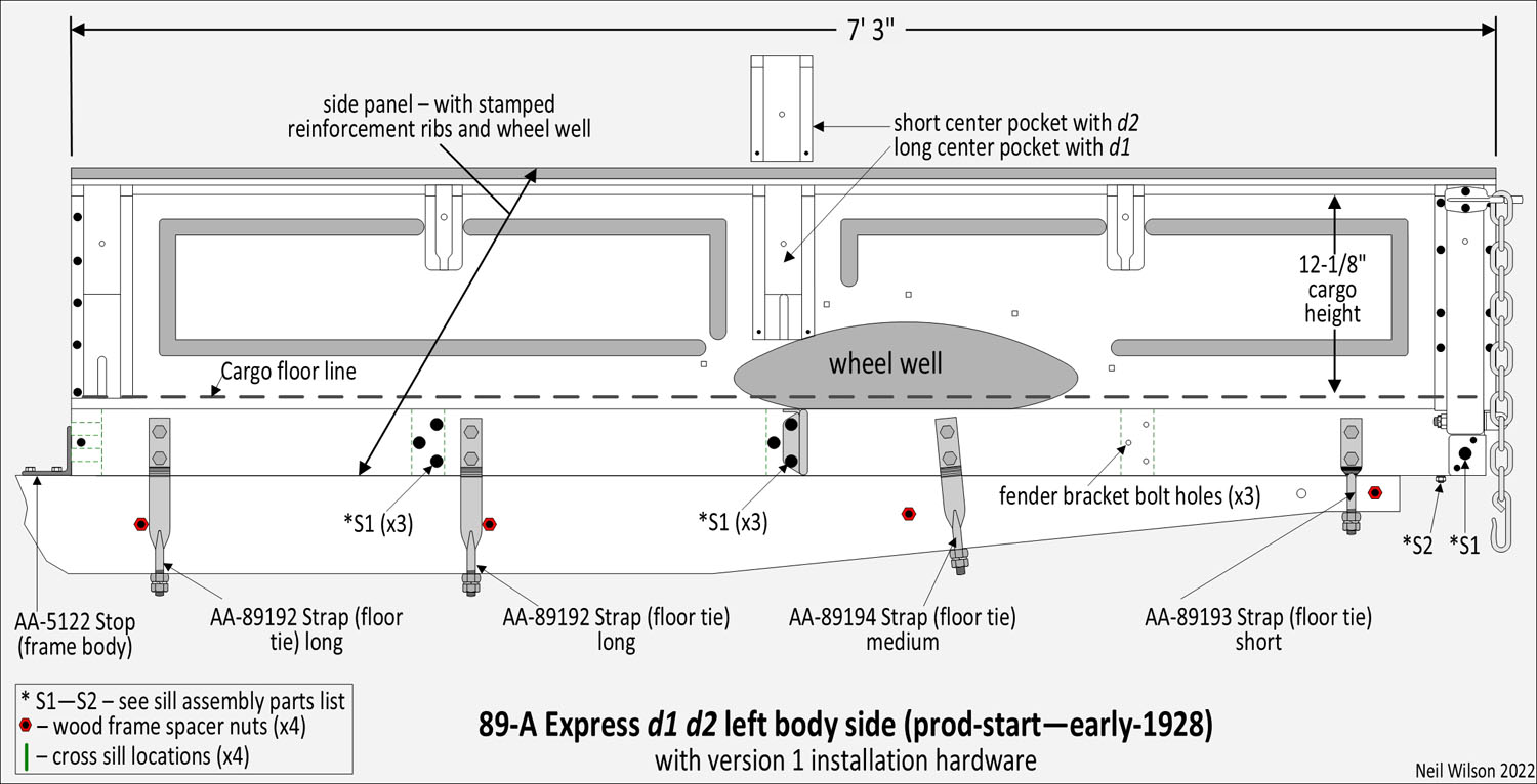
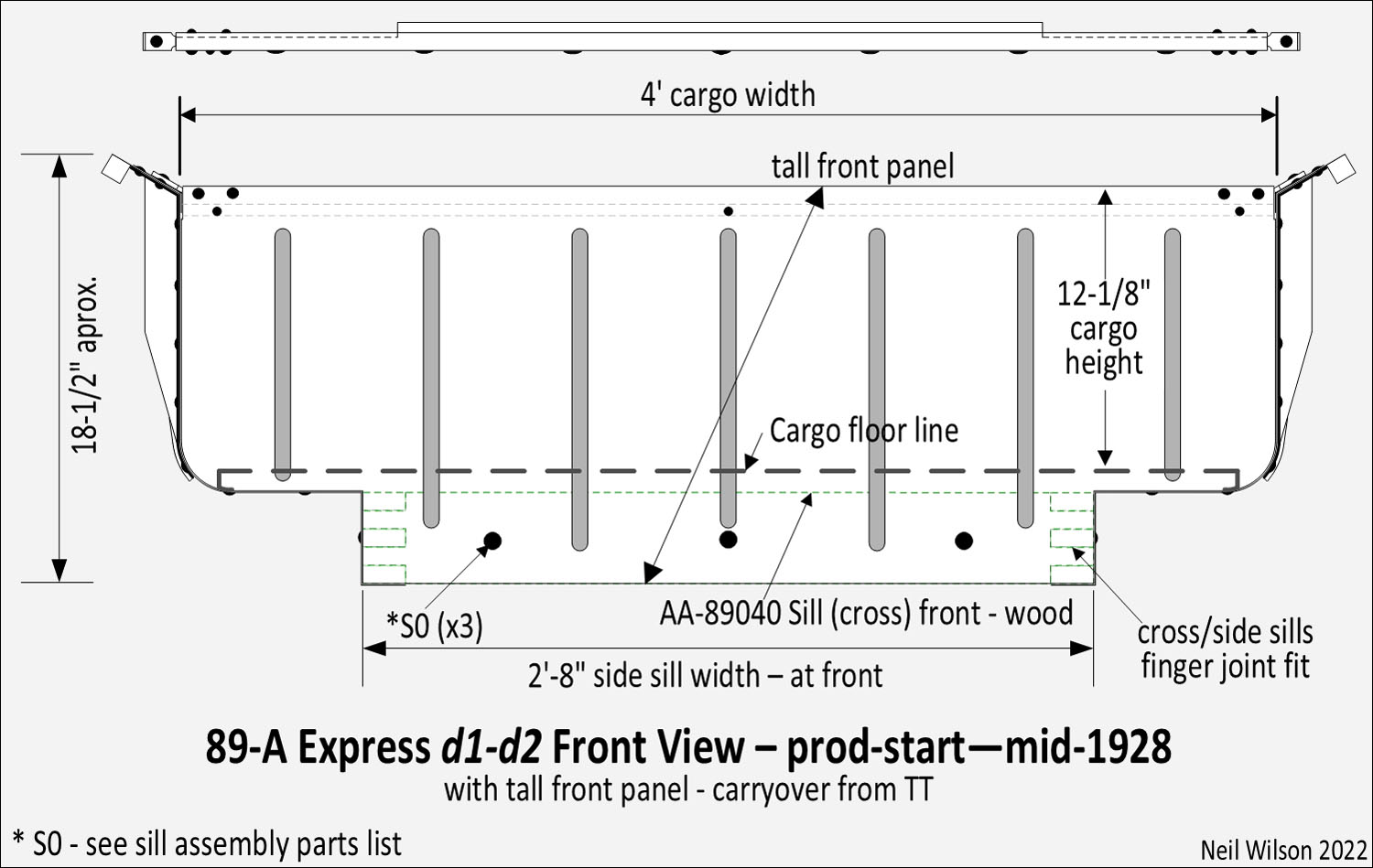
d1 – Tall front panel (TT carry-over) with a wooden front cross sill requiring all skid strips to be attached with wood screws at the front, center stake pockets extended to the wheel wells requiring notched rear fenders, four pair of installation tie straps per side requiring double notched running board shields for tie strap clearance, and frame installed body stops.
d2 – Center stake pocket shortened in early-1928. Resulted in new rear fenders without center stake pocket notches (same fenders as used on the 85-A panel delivery and 88-A platform).
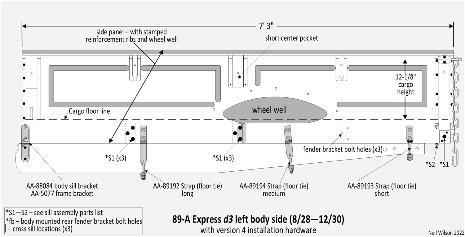
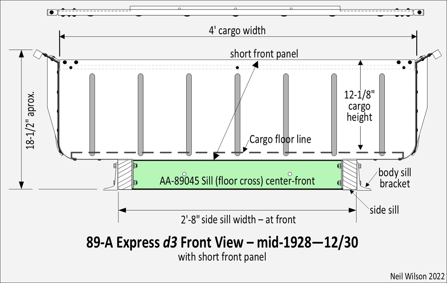
d3 – Front panel shortened starting August 1928. Resulting in elimination of the wooden front cross sill, modified skid strip which attached to the front panel flange with carriage bolts, elimination of body stops, and replacement of front installation tie straps with body sill brackets. With the change in installation hardware, each running board shield was changed to eliminate the front tie strap notch and two holes were added for body sill bracket bolts.
89-A Express d1—d3 Summary Gallery
89-A Express Front Panel Assembly – to parts listing
The “89-A Express Front Panel Assembly Gallery” below shows the two front panel designs.
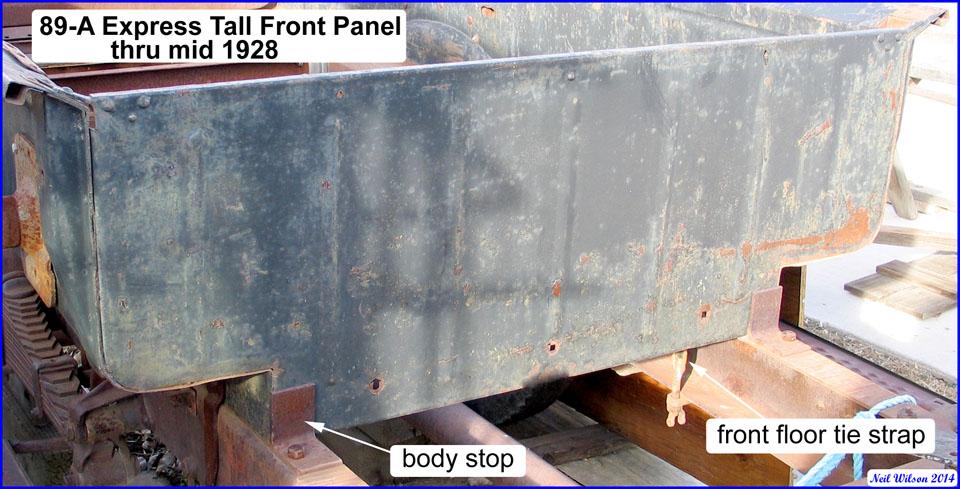
The initial front panel was a carry-over TT express part and is referred to as the “tall front panel” in this documentation. The panel’s bottom edge extended to the bottom of the body with a flange which turned under the front cross sill. There were seven vertical reinforcement ribs stamped in this panel. The top edge of the panel formed a 3/4” box for added strength. At each end of this box, a bracket was inserted and attached by two rivets. The brackets extended out, resting on top of the side-panel-flares and were each attached by one rivet. Additional rivets attached the front panel to each side panel.
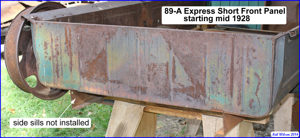
The second front panel design (referred to as the “short front panel” in this documentation) was 4″ shorter than design one. It was used in production starting in mid-1928. This change resulted in:
- Shortening of the five center reinforcement ribs
- Elimination of the wooden front cross sill (with side sill, finger joint machining eliminated)
- Usage of body sill/frame brackets (eliminating body stops and the front floor tie straps)
The bottom edge of this d2 front panel turned under the cargo floor, forming a 1-3/16” flange which supported the floor boards. The cargo floor’s corrugated steel batten-strips (i.e. skid strips) were bolted through this flange, unlike the d1 design in which the strips were attached with screws to the wooden front cross sill. A new part number was not assigned to this shortened panel. Consequently, the d2 front panel would have been provided for any service part order.
89-A Express Front Panel Assembly Gallery

89-A Express Tail Gate Assembly – to parts listing
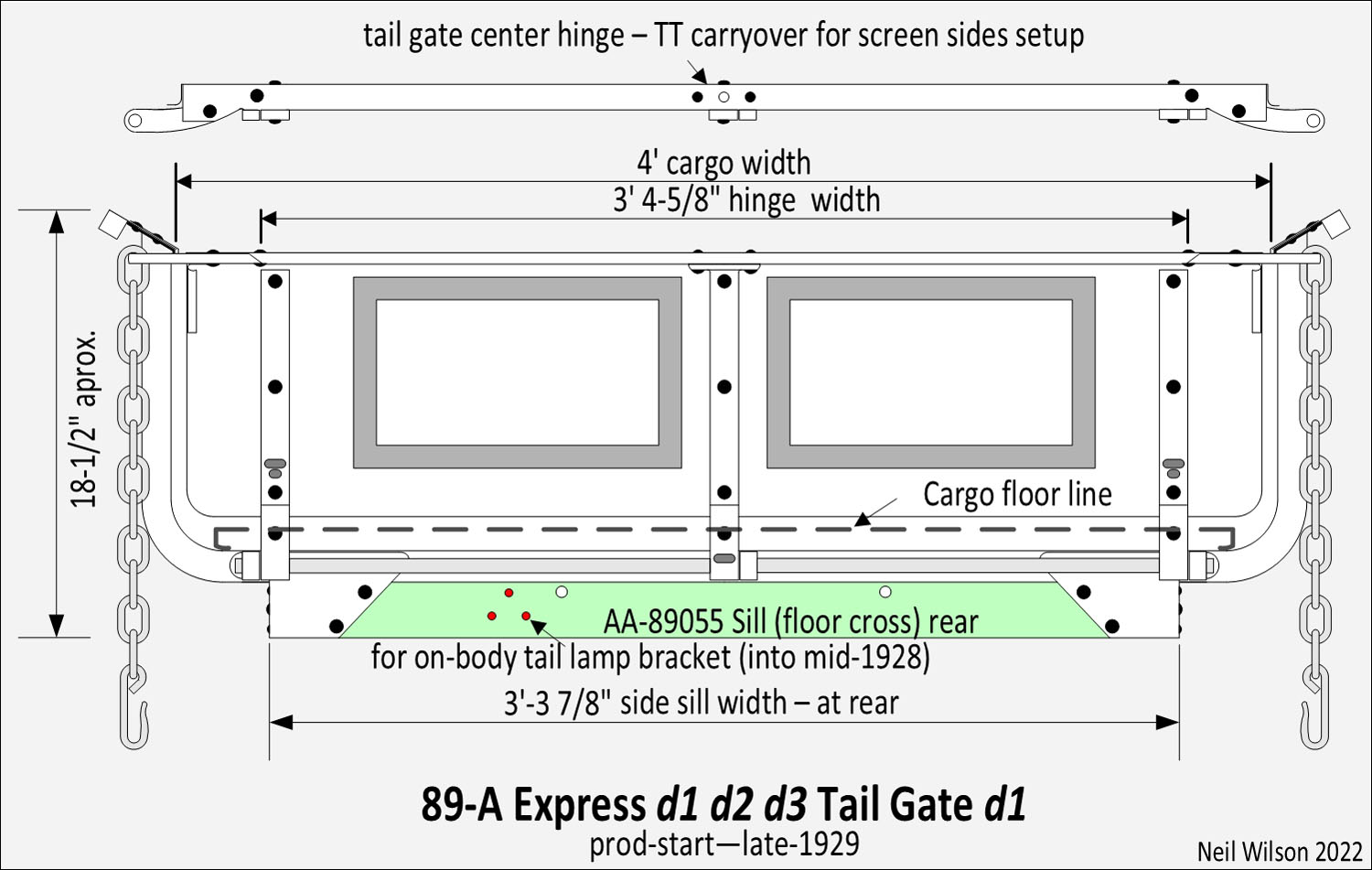
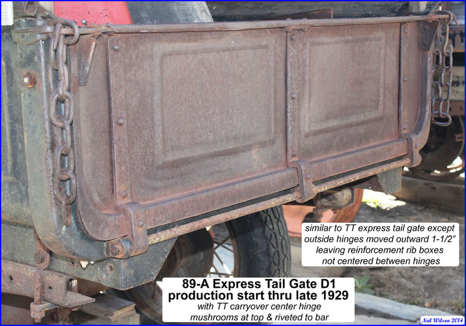
The TT and AA express tail gates were the same except for the location of the two outside hinges. For the AA, these hinges were placed 1-1/2” closer to each side as a result of the 89-A express being converted to tapered side sills.
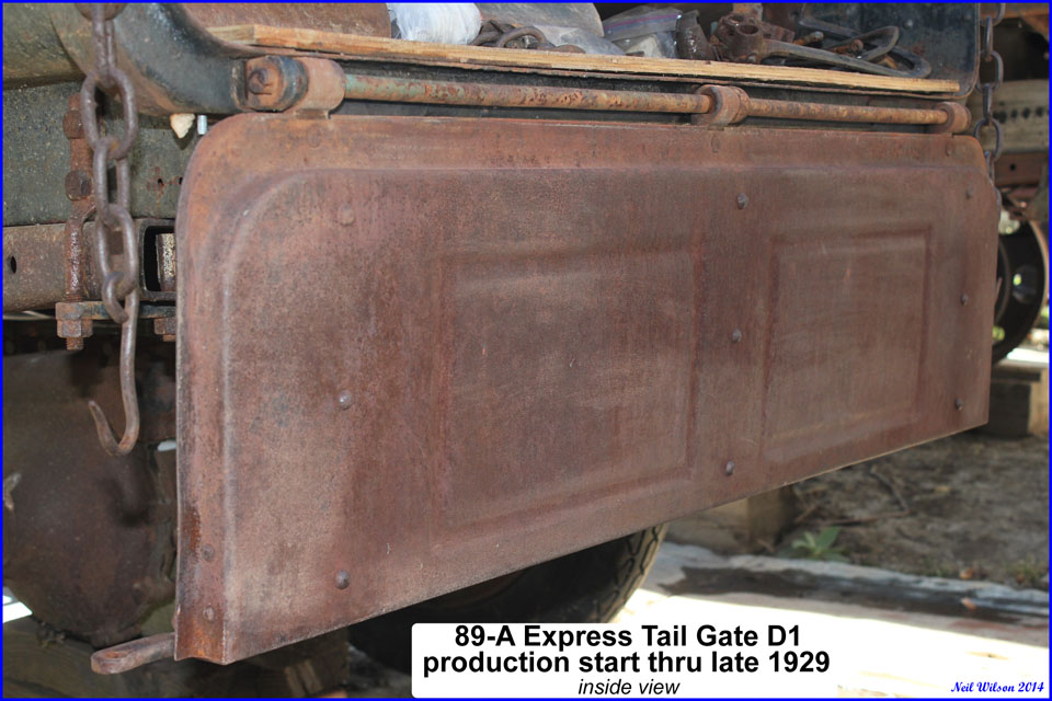
The two rectangular-shaped reinforcement ribs stamped into the tail gate panel were centered between the TT hinges. Because these rib locations were not changed for the AA, the ribs were unevenly centered between hinges.
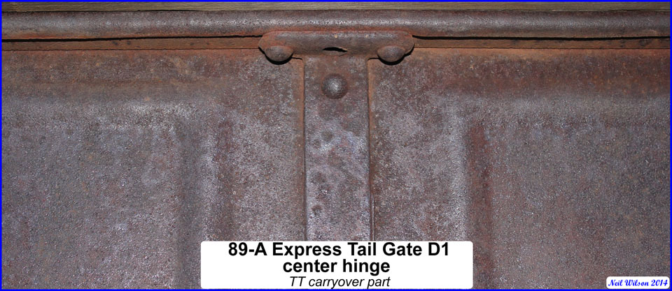
Like the TT, the center hinge, shown in the galley below, extended up to the tail gate bar where it mushroomed to form a small support area. This hinge was riveted to the tail gate bar. There was a 7/16” hole through the top of the tail gate panel, bar and hinge. This hole was used for TT canopy screens to secure the screen doors with a rod. Canopies were not offered with the 89-A express. Consequently, this special center hinge set-up was simply a TT carry-over part and assembly process.
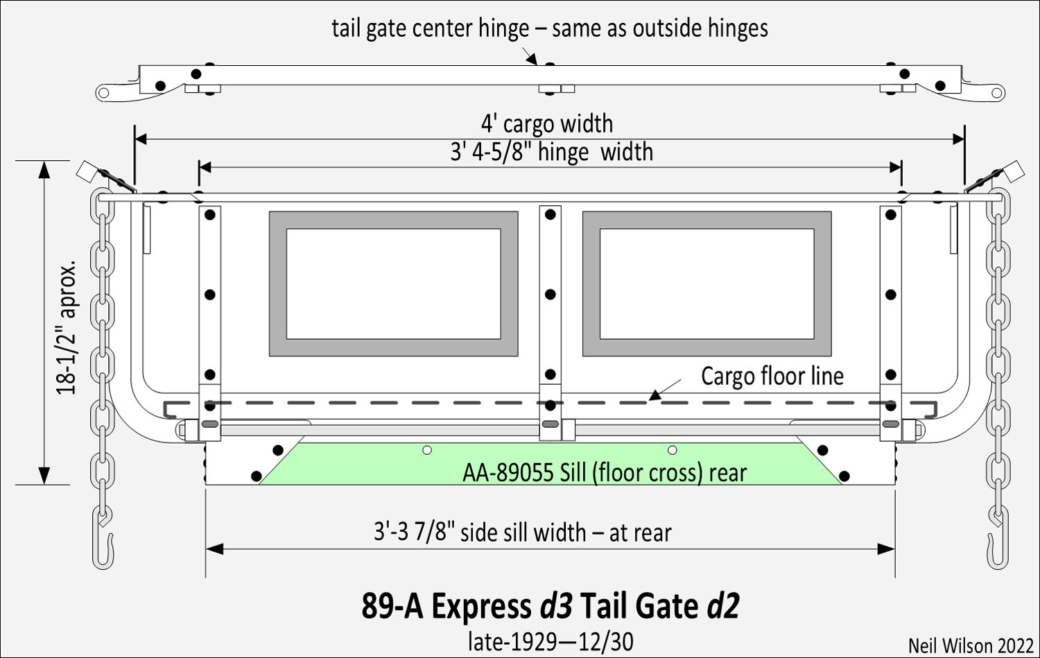
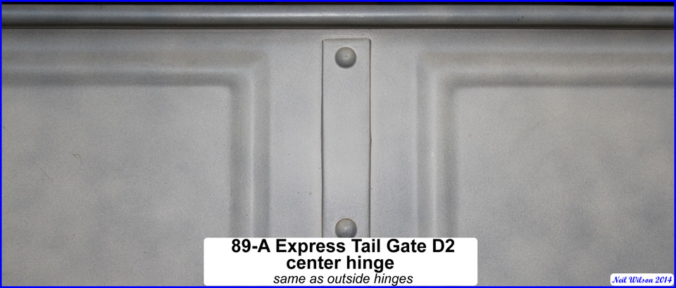
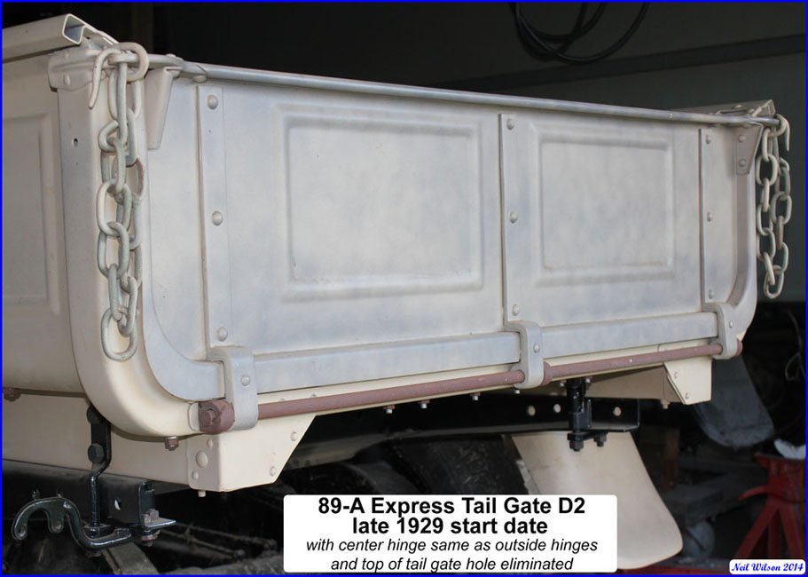
In late-1929 the center hinge was change to be the same as the outside hinges and the latch hole for the canopy screen was eliminated.
Note that customers could have installed the TT canopy top and screens on their 89-A express truck. The TT canopy top was higher than the top of the 82-A cab.
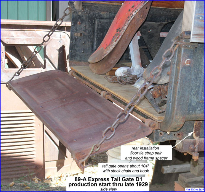
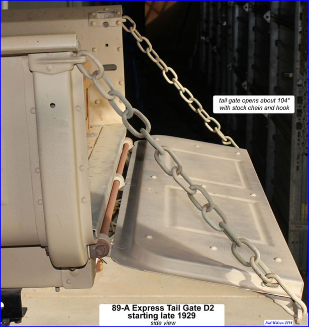
The tail gate chain links were made of 5/16” thick stock. They were 2-5/16” long x 1-7/16” wide. The twelve links were 19” long. With the 3-3/4” long hook, the total assembly was 22-1/4” long. The chain assembly allowed the tail gate to open about 104° rather than 90° like the 78-A pickup tail gate. A sheath covered the chain.
The tail gate was installed on the side panel #3 support with three body hinges and a tail gate rod. The rod was held in position with a cotter pin on each end.
89-A Express Tail Gate Assembly Gallery
The center hinge design determines the d1 or d2 tail gate as shown below.
Tail Gate Assembly d1 Images
Tail Gate Assembly d2 Images
89-A Express Side Panel Assemblies – to parts listing
The 89-A express flared, side panel was a one piece stamping which included stamped reinforcement ribs and a stamped wheel well. The panels wrapped the wooden side sills on their outside and bottom edges. The horizontal section of the side panel stamping (the portion below the outside floor board) was tapered to allow the express body to rest on the frame. A side panel assembly included the the following parts:
- side panel stamping
- side panel supports #1 (front stake pocket)
- side panel supports #2 (center stake pocket)
- flare reinforcements (two of them)
- side panel reinforcement (triangular shaped, attached below the wheel well)
- side panel supports #3 (formed rear stake pocket)
- side panel to support #3 bracket assembly
- stake pocket plates (three of them)
Stake pockets and plates were spot welded and riveted to the side panel. Centered between stake pockets, the flare reinforcements were spot welded and riveted in place. Below the wheel well, the triangular reinforcement was riveted to the horizontal plane of the side panel and bolted to the side panel sill area.
Each side panel had holes punched for cross sill bolts and body installation hardware. Starting in August 1928, with the conversion to the short front panel, changes to hole locations were made to accommodate a new version of installation hardware.
The front pockets were about the same as used on the TT express (as well as the T and A pickup bodies).
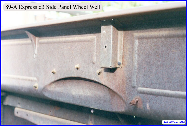
The initial d1 center pocket extended to the wheel well. This required that the rear fender have a reinforced notch to fit around the pocket. The d2 center pocket was used starting in early-1928. This pocket was shorter and had a squared-off bottom which stopped above the rear fenders. The notch of the rear fender was thus eliminated with this change. Oblong, pocket drain holes were punched in the side panels. The short d2 pocket required that the drain hole to be moved up about 2”.
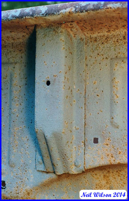
Note that during the initial center pocket conversion (i.e. d1 conversion to d2), a few side panels were punched with both center pocket drain holes. The lower hole was covered with a piece of square metal riveted to the outside of the panel.
89-A Express Side Panel Assemblies Gallery
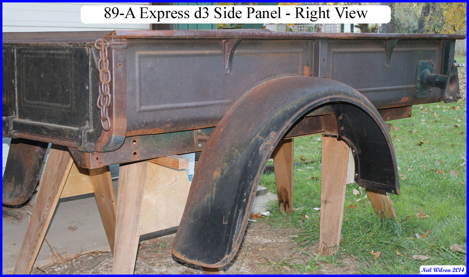
The right and left side panel assemblies were installed with rivets to the front panel and the #3 panel support at the rear.
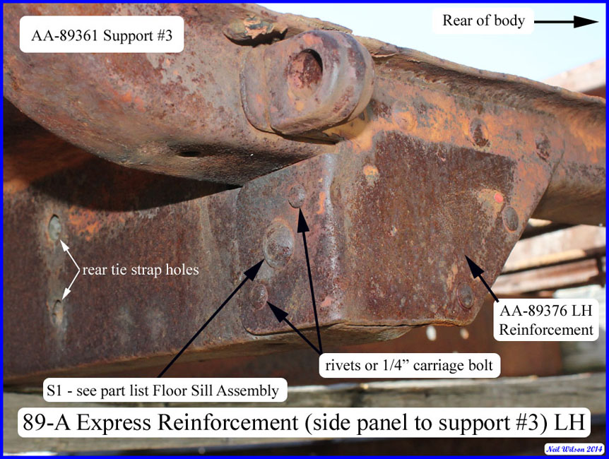
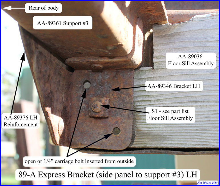
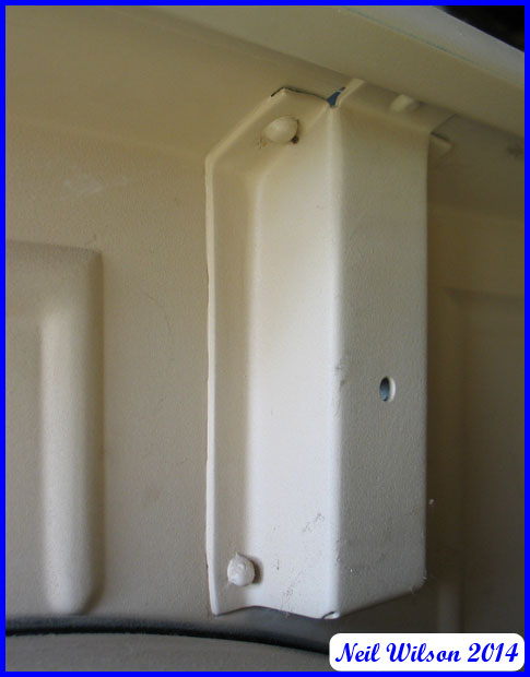
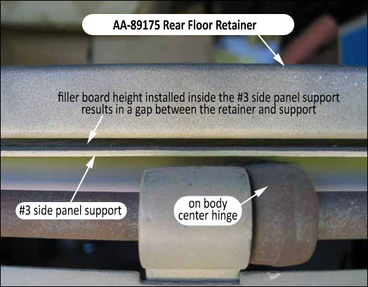
The #3 side panel support was u-shaped and formed the rear stake pockets, supported both the side panels and the cargo floor. It held the short (on body) tail gate hinges and the tail gate chain brackets were riveted to this support. Inside the bottom of the support channel, a wooden filler was inserted prior to the side panels being installed. This filler was flush with the horizontal plane of the side panels, side sills, and cross sills. Therefore the filler was slightly higher than the support.
Without this filler, the floor boards would not lie flat and the rear floor retainer would rub against the #3 support.
The #3 side panel support had AA-89343/44 left and right assemblies riveted in place. These assemblies included two parts riveted together
- AA-89345/46 left and right brackets were installed on the bottom side of the #3 side panel support and covered the inside face of the wooden side sills.
- AA-89375/76 left and right reinforcements were riveted to the rear face of the #3 side panel support. They covered the rear end of the wooden side sills and wrapped the face of the side panel. The outside, on-body, tail gate hinges were installed through these reinforcements.
89-A Express Floor Sill Assembly – to parts listing
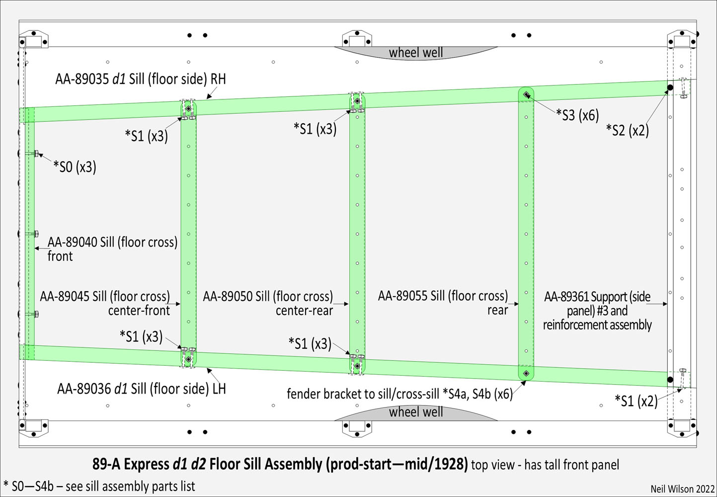
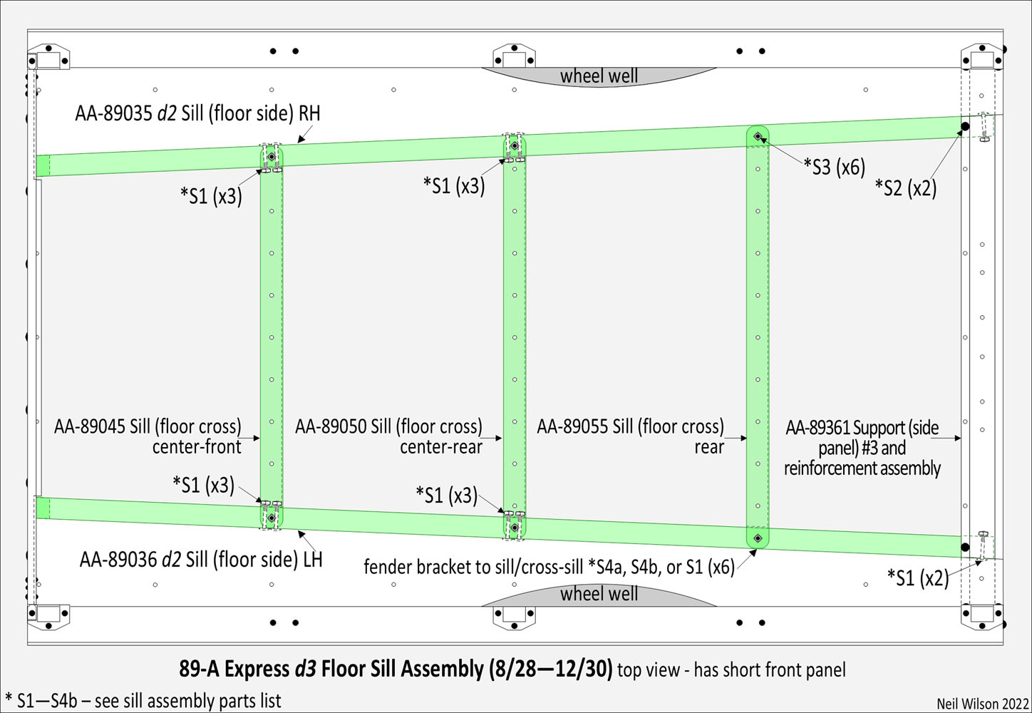
The sill assembly formed a base for attaching the cargo floor. There were two designs of the floor sill assemblies (d1 and d2). Express bodies with the tall front panel used the d1 floor sill assembly (with d1 side sills plus a wooden front cross sill). Express bodies with the short front panel used the d2 floor sill assembly (with d2 side sills and no front cross sill). The Floor Sill Assemblies Gallery shows details of the floor sill assembly which consisted of side sills and cross sills installed as a unit during the body assembly process.
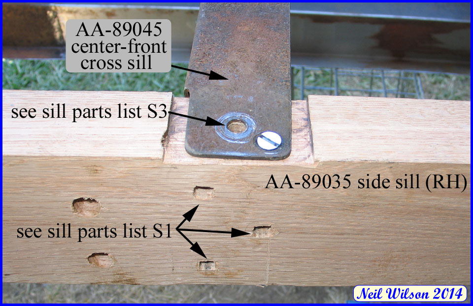
The assembly was installed in the body with a carriage bolt at the #3 side sill support (see S2 of the galley drawings). In addition, flat head slotted bolts were used at the location of each of the three metal cross sills (see S3 of the galley drawings). These bolts were inserted from the bottom flange of the side panel, up through the side sill. This left the nuts/locks for the bolts extended above the side sills. Flat bottomed holes in the bottom of the intermediate floor boards allowed the boards to lie flat and conceal the sill installation hardware.
Side Sills
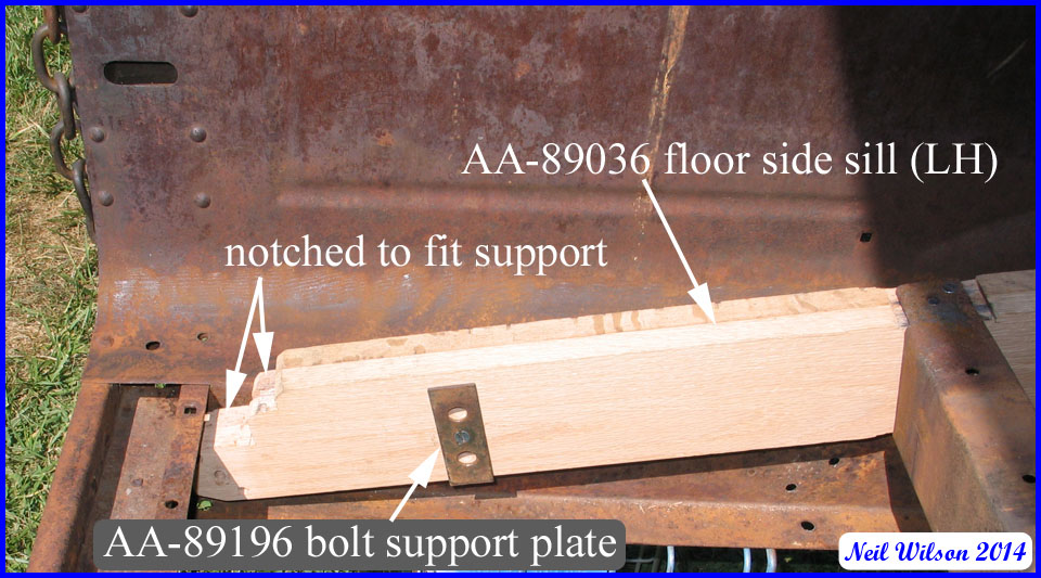
Original AA-89036 (d1—d2) LH and AA-89035 (d1—d2) RH side sills observed were made of yellow pine (like the floor boards). The side panels clad the outer and bottom sides of these sills. At the rear of each side sill was a double notched to allow the sills to fit under the u-shaped #3 side panel support. The outside-lower edge of each side sill was chamfered to allow a good fit to the side panel. Side sills were machined for sill to side panel bolts, cross sill installation bolts, and body to frame installation hardware.
At the location for each of the three metal cross sills, the side sills were notched (top and bottom) for cross sill installation.
The body to frame installation hardware sill plates (bolt support plates) were installed as part of the side sill.
When the front cross sill was eliminated at the end of July 1928, the d2 side sills replaced the d1 side sills. For the new d2 side sills finger joint machining of the side sills was eliminated and the sills were drilled for the version 4 installation hardware.
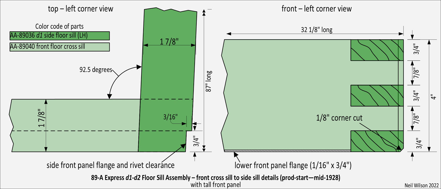
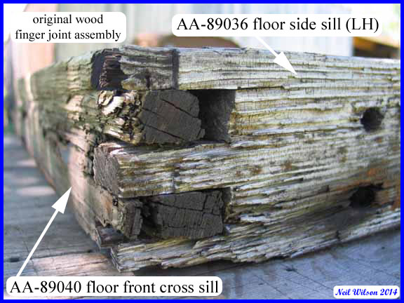
Front Cross Sill AA-89040
This wooden front cross sill was used with express bodies with the tall front panel. It was the same cross sill used for the TT express body. This front cross sill and the side sills were machined with finger joints to interlock them together.
In addition, there were three bolt holes drilled for attachment of the cross sill to the front panel. This wood front cross sill was eliminated when the front panel was shortened.
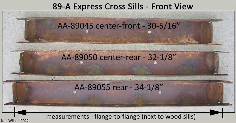
Cross Sills AA-89045 50 and 55
The remaining three cross sills were stamped steel. The Ford assigned names for these cross sills were:
- Center-Front cross sill – AA-89045
- Center-Rear cross sill – AA-89050
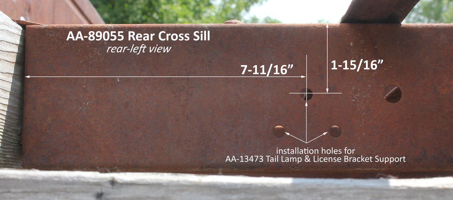
- Rear cross sill – AA-89055
They were c-shaped with the open side facing forward. Unlike the TT, each of the AA express cross sill was progressively wider to fit between the tapered side sills. The top flange of each cross sill had holes punched for cargo floor attachment bolts.
Initially, the rearward face of AA-89055 rear cross sill was punched with holes for an on-body tail lamp support. When the tail lamp support was changed to a frame installation, the cross sill holes were eliminated without a change in the part id.
Prior to installing the sill assembly in the body, the cross sills were attached to the side sills with flat head slotted wood screws at the top and bottom. When the sill assembly was installed in the body, three triangularly arranged carriage bolts were used, as shown in the gallery, to connect the sides, side sills, and cross sills as a unit.
89-A Express Floor Sill Assemblies Gallery
89-A Express Cargo Floor – to parts listing
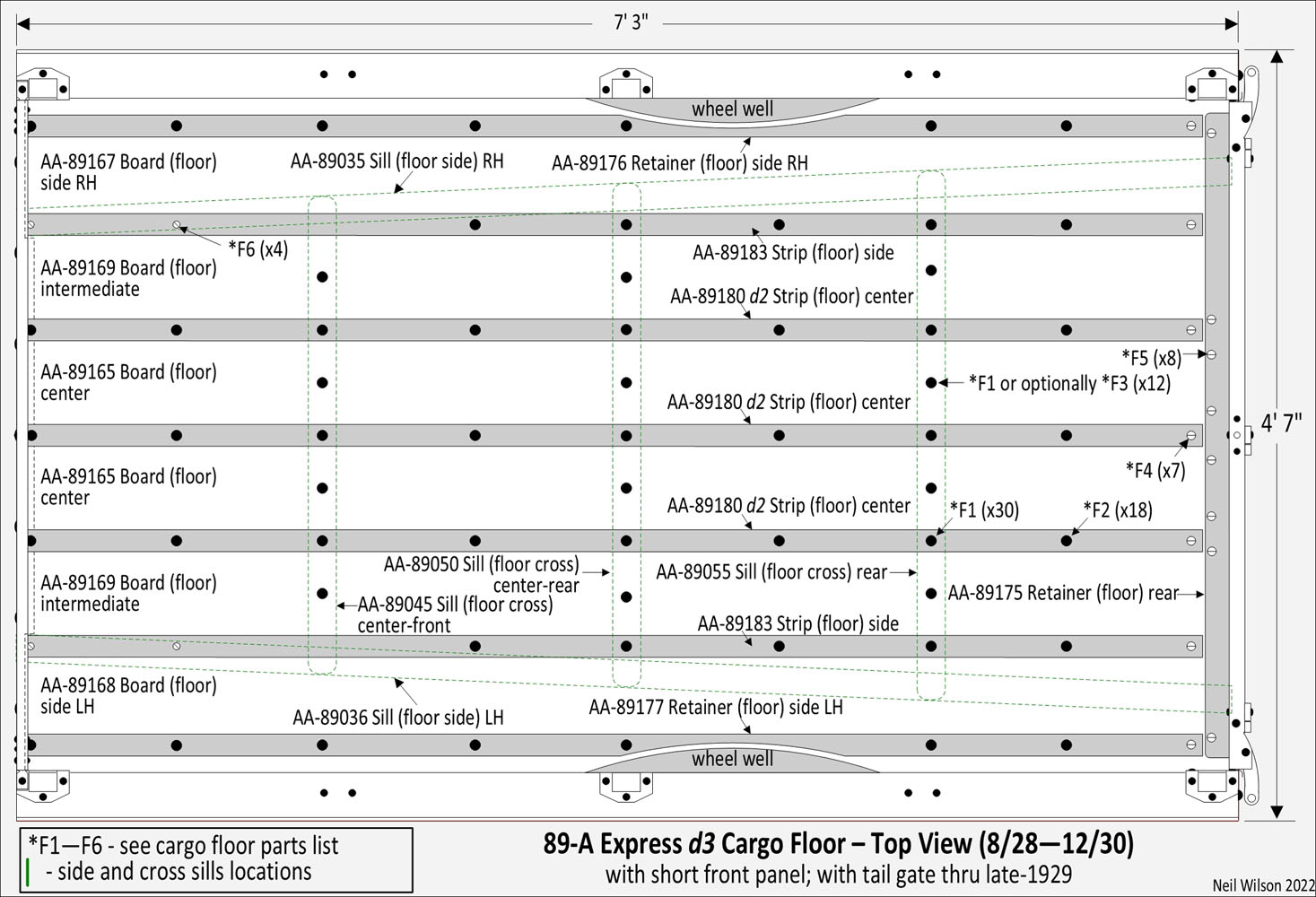
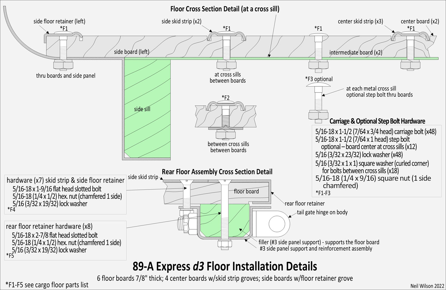
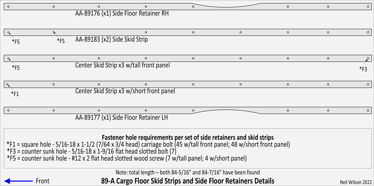
There were two designs of the cargo floor (d1 and d2). Express bodies with the tall front panel had the d1 cargo floor and used d1 center skid strips. Express bodies with the short front panel had the d2 cargo floor and used d2 center skid strips. The cargo floor consisted of six floor boards, five skid strips, side floor retainers (right and left hand), and one rear floor retainer.
All of these parts were attached to the body with various hardware (carriage bolts, flat head slotted bolts, and flat head slotted wood screws).
Note that the cargo floor was installed prior to painting. So, any finish applied to sub-parts and installation hardware was covered by the final painting operation (including the bottom of the body).
Floor Boards
Original cargo floors observed have had yellow pine boards. Other types of wood may have been used. These boards were 7/8″ thick, 7-3/16″ wide and 86-5/8″ long. The boards were grooved to allow the legs of the skid strips or side floor retainers to rest in the grooves. The groves were normally on both sides of the boards (bottom groves served no purpose).
The rear of each board extended past the skid strips to the rear of the #3 side panel support. All boards were notched on the bottom-rear edge to accommodate the rear floor retainer which wrapped the rear of the six boards. All boards were drilled for the board to cross sill center bolts (three per board). The remaining machining of the floor boards was as follows:
AA-89165 Center Boards – these two boards were machined to accommodate two rear floor retainer flat head slotted bolts.
AA-89169 Intermediate Boards – The bottom-fronts were notched to allow clearance of the front panel flange. And they were machined to accommodate one rear floor retainer flat head slotted bolt. To avoid having a left and right board, machining was duplicated on these boards. So, there were two bottom-front notches and two rear floor retainer bolt holes.
AA-89168 LH and AA-89167 RH Side Boards – The bottom-fronts were notched to allow clearance of the front panel flange. And they were machined to accommodate one rear floor retainer flat head slotted bolt. The bottom-outside edges were rounded to follow side panel curvatures.
Each board was cut to follow the wheel well radius. The bottoms of the boards were machined with relief holes to fit over the three protruding sill assembly bolts-nuts. The boards were drilled to accommodate the eight bolts used to attach the side floor retainers.
Side Floor Retainers
Parts AA-89177 LH and AA-89176 RH. The outside edge of each board was attached to the side panels with a floor retainer. Retainers were bolted through the boards and the horizontal surface of the side panels.
The outside edge of the floor retainers wrapped the board and had the same radius at the wheel well.
Rear Floor Retainer
The AA-89175 retainer wrapped the ends and bottom of the six floor boards. It was attached with eight flat head slotted bolts.
Bolts extended through the retainer, floor boards, #3 side sill support filler, and the #3 side sill support.
Skid Strips
A skid strip straddled the 5/16″ gap between floor boards. The skid strips were secured by a combination of carriage bolts, flat head slotted bolts (at the rear), and flat head slotted wood screws. Strips were punched with square or countersunk holes to match the appropriate hardware. The two AA-89183 outside skid strips were located above the tapered side sills at the front and were therefore attached with wood screws (2 per strip). For express bodies with the tall front panel, the center d1 skid strips were screwed to the wooden front cross sill.
Express bodies with the short front panel had the center d2 skid strips attached with carriage bolts to the front panel.
Note – because side boards did not fit tight against the vertical side panels, a small trough existed which collected dirt and water leading to rust-out of the side panels in this area. The 87-A pickup was designed differently and did not have this problem.
89-A Express Cargo Floor Gallery
89-A Express Installation Hardware
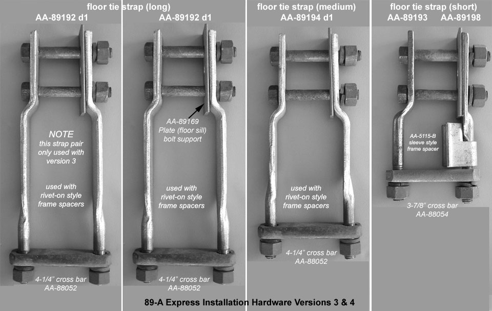
The 89-A express installation hardware included sets of floor tie strap pairs. 89-A Express d1 and d2 used four pair of straps per side. 89-A Express d3 used three pairs of straps plus a body-sill-to-frame bracket per side. The gallery below this hardware.
For a given 89-A Express installation, floor tie straps plus frame parts were used in combinations of five versions as shown in the Hardware-Versions-Table following. Each version is based on both the express body front panel design and frame design of a given AA express truck.
The conditions of these two items dictated which installation hardware versions was used for the truck.
The express body and frame used on the assembly line would have varied at the assembly plants due to shipping and usage. Consequently, the hardware version usage dates shown in the table are approximate production dates only.
The various frame parts used for either an 88-A Platform or 89-A Express installation are found on the Frame Brackets page. The following are direct links to the various parts associated with 89-A Express installations:
89-A Express Installation Hardware Gallery
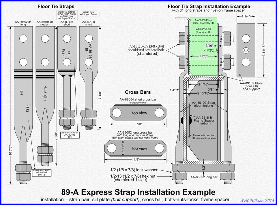
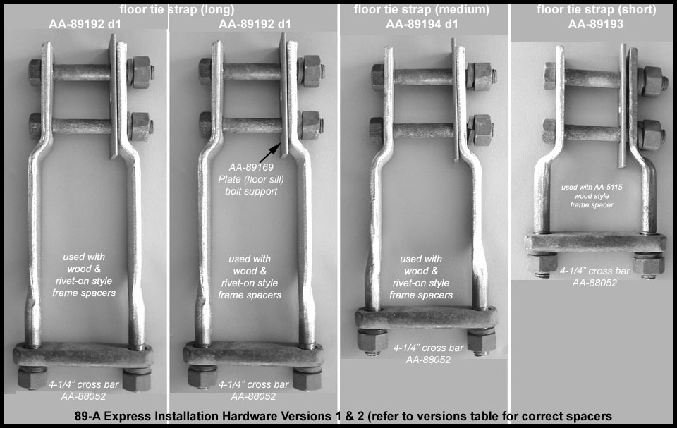
Floor Tie Straps
The 89-A Express Installation Hardware Gallery shows examples of floor tie strap designs and various installations.
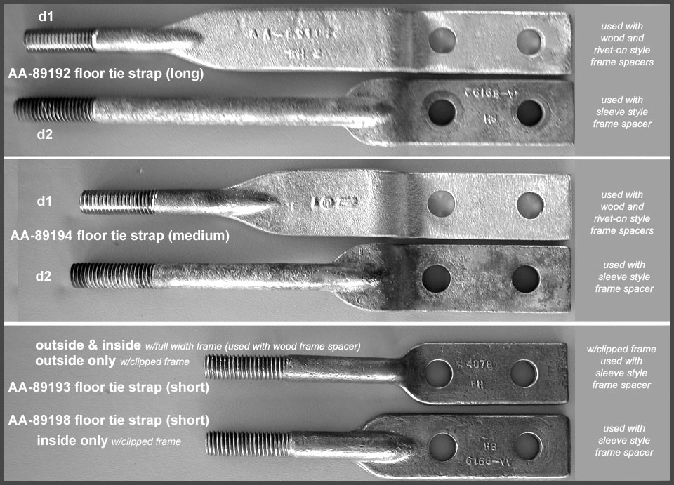
The black painted floor tie straps came in three lengths (long, medium, and short) for installation at different locations along the frame. There were two designs (d1 and d2) for each of the long and medium straps. Straps were forged steel with an upper section which was 1-1/4” wide by 1/4” thick. The strap lower section was 1/2″ round with 1/2-13 threads at the lower end. The d1 floor tie strap round section extended 2-1/2″ from the bottom. The round section of the d2 floor tie strap was lengthened to allow for the usage of a sleeve style frame spacer and was specified to start 3-13/16″ from the top.
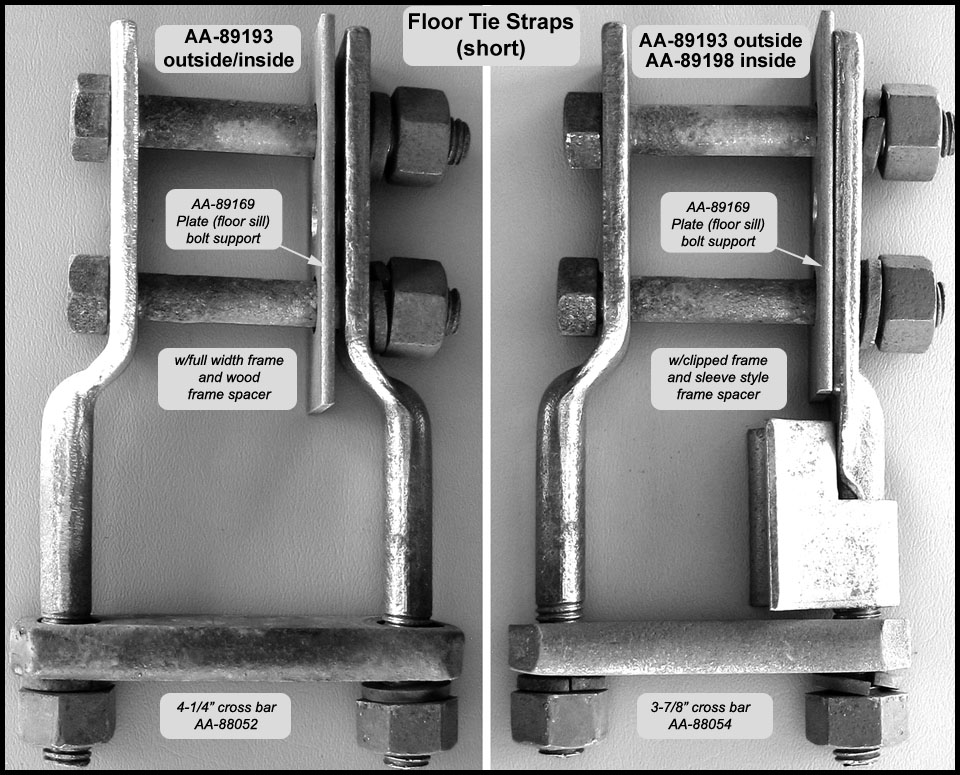
For installation, pairs of straps were bolted to the outside and inside of the express body side sills using two 1/2” shouldered bolts (inserted from the body outside). When installed, the straps extended below the bottom of the frame. A cross bar tied the two straps together under the frame and the assembly was secured to the frame with 1/2-13 nuts and lock washers.
A bolt support plate was sandwiched between each inside floor tie strap and the wood body side sill. Plates extended to the bottom of the body and rested on top of the frame side members.
When a strap pair was tightened to the frame, the plate supported the two strap to body bolts (protecting the wood body sills). Each plate was attached with one slotted, flat head wood screw prior to painting.
Each pair of straps used a long cross bar (AA-88052) except the rear strap pairs in hardware installation versions 3-5 which used a short cross bar (AA-88054). The black painted cross bars had clipped corners and flat or rounded sides. Each strap pair used two hex nuts and lock washers to tighten the cross bar to the bottom of the frame. Note that the cross bars were also used on the 88-A platform and assigned 88-A body part numbers.
Into mid-1928, the rear tie strap pairs used part number AA-89193 for both the inside and outside tie straps. Starting about April 1928, the rear of the frame side members were given a tapered clip which reduced the side member’s width at the rear. As a result, new floor tie strap AA-89198 became the inside straps at the rear. The new strap extended straight down from the body sill. This was unlike all other straps which were “dog leg” in shape as shown in the 89-A Express Installation Hardware Gallery. This new inside strap was designed to use sleeve spacer AA-5115-B and replaced the AA-5115 wood frame spacer.
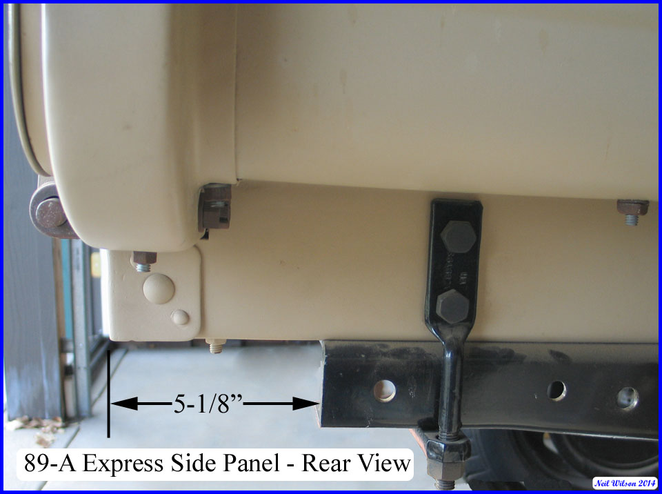
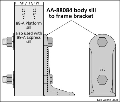
Body Sill to Frame Bracket
This bracket was used for the installation of Ford sold platforms as well as the 89-A and 242-A express bodies (two per body type). For the 89-A, these brackets were used with the short front panel of the d3 body. A corresponding AA-5077 frame to body-sill bracket was rivet to the frame. The change to use this bracket combination occurred in August 1928 (approximately).
These brackets replaced both frame body stops as well as the front 88-A U-bolts and 89-A floor tie straps as the forward installation hardware. The 89-A Express Installation Hardware Gallery shows detailed installation of bracket AA-88084. This bracket was bolted to the sides of each sill prior to painting. Frame bracket AA-5077 was riveted to each outside face of the frame prior to frame painting. When the body was mounted to the frame, the brackets were bolted together.
89-A Express Related Parts
89-A Express Wheel Carrier
The spare wheel carrier was located on the right side of the body toward the front. The spare tire rested on the running board and was between the cab door and the rear fender. The initial carrier was riveted to the body side and had two designs.
A frame mounted carrier was used starting in early-1929. A re-designed frame mounted carrier was used with the new wheels released January of 1930. Wheel carriers were listed as AA chassis parts by Ford. Check out the AA-1400 Wheel Carrier information.
89-A Express Rear Fenders, Brackets, Spacers
The rear fender were initially designed with a reinforced notch to fit around the 89-A express long center pocket. The center pocket was shortened to be above the rear fender and the notch was eliminated. This re-designed fender was also used on the 85-A panel delivery and was an option on the 88-A platform through July 12, 1929.
With the change over to the new 1930/1931 style sheet metal in June of 1930, the rear fender was modified to fit the new design running board shields. The rear fender bracket was unique to the 89-A express and the 88-A platform. There was a unique rear fender spacer for the 89-A. Fenders, brackets, and spacers were listed as AA chassis parts by Ford. Check out the AA chassis fender information page.
89-A Express Tail Lamp Support Brackets
Two designs of AA unique supports were initially installed on the express body rear cross sill (AA-89055). The support was later moved to the frame and was also unique to the AA.
In mid-1928 the A chassis support was used on the AA. Supports were listed as A and AA chassis parts by Ford. Check out the AA chassis electrical system information.
89-A Express Parts Listing
| # | Part | Part Description |
|---|---|---|
| Neil Wilson 2014 | ||
| 1 | AA-89000 | Express Body Assembly d1—d3 (includes front panel, tail gate, side sills, and cargo floor assemblies) |
| 89-A Front Panel Assembly | ||
| 1 | AA-89405 | d1 Panel (front) assembly – tall 12/27—7/28 (was TT-12056-X) |
| d2 Panel (front) assembly – short 8/28—12/30 | ||
| 2 | AA-89420 | Bracket (front panel to side panel) (was TT-12034-X) (w/assembly AA-89405) |
| 89-A Tail Gate Assembly | ||
| 1 | AA-89500 | d1 Gate (tail) assembly – center hinge TT carryover (12/27—lt/29) |
| d2 Gate (tail) assembly – center hinge = side hinges (lt/28—12/30) | ||
| 1 | AA-89505 | Panel (tail gate) (w/assembly AA-89500) |
| 1 | AA-89540 | Bar (tail gate) (w/assembly AA-89500) |
| 2 | AA-89550 | Hinge (tail gate) side long (was TT-12005-X) (w/assembly AA-89500) |
| 1 | AA-89555 | Hinge (tail gate) center long – (12/27—lt/29) was TT-12087-X (w/assembly AA-89500 d1) |
| 1 | AA-89550 | Hinge (tail gate) center long – lt/28—12/30 (w/assembly AA-89500 d2) |
| 3 | AA-89552 | Hinge (tail gate) short – on body (was TT-12006-X) |
| 3 | 1/2-20 (9/16 x 3/4) castle nut | |
| 3 | 3/32 x 3/4 cotter | |
| 1 | AA-89557 | Shim (center short tail gate hinge) (was TT-12025-X) |
| 1 | AA-89561 | Rod (tail gate hinge) (5/8 x 43-1/8) |
| 2 | 1/8 x 1-3/8 cotter | |
| 2 | AA-89525 | Chain (tail gate) and bracket assembly |
| 1 | AA-89542 | Bracket (tail gate chain) |
| 2 | AA-89565 | Sheath (tail gate chain) assembly (was TT-12076-X) |
| 1 | AA-89566 | Sheath (tail gate chain) outer |
| 1 | AA-89568 | Sheath (tail gate chain) inner |
| 89-A Side Panel Assemblies | ||
| 1 | AA-89304 | d1 Panel (side) assembly RH (12/27—er/28) long center pocket with tall front panel |
| d2 Panel (side) assembly RH (er/28—7/28) sort center pocket with tall front panel | ||
| d3 Panel (side) assembly RH (8/28—12/30) with short front panel | ||
| 1 | AA-89305 | d1 Panel (side) assembly LH (12/28—er/28) long center pocket with tall front panel |
| d2 Panel (side) assembly LH (er/28—7/28) short center pocket with tall front panel | ||
| d3 Panel (side) assembly LH (8/28—12/30) with short front panel | ||
| 1 | AA-89312 | Panel (side) RH (w/assembly AA-89304) |
| 1 | AA-89313 | Panel (side) LH (w/assembly AA-89305) |
| 4 | AA-98328 | Plate (side panel pocket) front & center (at top of flare) (w/assemblies AA-89304/05) |
| 2 | AA-98330 | Plate (side panel pocket) rear (at top of flare) (w/assemblies AA-89304/05) |
| 1 | AA-89362 | Support (side panel) #1 RH – front pocket RH (w/assembly AA-89304) |
| 1 | AA-89363 | Support (side panel) #1 LH – front pocket LH (w/assembly AA-89305) |
| 2 | AA-89364 | d1 Support (side panel) #2 – center pocket (12/27—er/28) extends to wheel well (w/assemblies AA-89304/05) |
| d2 Support (side panel) #2 – center pocket (er/28—12/30) to rear fender (w/assemblies AA-89304/05) | ||
| 4 | AA-89350 | Support (side panel flare) (w/assemblies AA-89304/05) |
| 1 | AA-89320 | Reinforcement (side panel) small RH (at wheel well) (w/assembly AA-89304) |
| 1 | AA-89321 | Reinforcement (side panel) small LH (at wheel well) (w/assembly AA-89305) |
| 1 | AA-89361 | Support (side panel) #3 – “U” channel forms rear pockets (w/assemblies AA-89304/05) |
| 1 | AA-89370 | Filler (side panel support #3) wood (2 x 1-5/8 x 39-1/4) (w/assemblies AA-89304/05) |
| 1 | AA-89343 | Bracket (side panel to support #3) assembly RH (AA-89345 & AA-89375) (w/AA-89304) |
| 1 | AA-89344 | Bracket (side panel to support #3) assembly LH (AA-89346 & AA-89376) (w/AA-89305) |
| 1 | AA-89345 | Bracket (side panel to support #3) RH under #3 support (w/assembly AA-89343) |
| 1 | AA-89346 | Bracket (side panel to support #3) LH under #3 support (w/assembly AA-89344) |
| 1 | AA-89375 | Reinforcement (side panel support #3) RH at rear face of #3 support (w/assembly AA-89343) |
| 1 | AA-89376 | Reinforcement (side panel support #3) LH at rear face of #3 support (w/assembly AA-89344) |
| 89-A Floor Sill Assembly | ||
| 1 | AA-89035 | d1 Sill (floor side) RH wood (1-7/8 x 4 x 86) 12/27—7/28 with tall front panel |
| d2 Sill (floor side) RH wood (1-7/8 x 4 x 86) 8/28—12/30 with short front panel | ||
| 1 | AA-89036 | d1 Sill (floor side) LH wood (1-7/8 x 4 x 86) 12/27—7/28 with tall front panel |
| d2 Sill (floor side) LH wood (1-7/8 x 4 x 86) 8/28—12/30 with short front panel | ||
| Standard Parts – Side sills to side panels (at rear) – attachment | ||
| 2 | *S2 | 5/16-18 x 4-1/2 (7/64 x 3/4 head) carriage bolt – head covered by floor board |
| 2 | *S1 | 5/16-18 x 2-1/2 (7/64 x 3/4 head) carriage bolt |
| 1928—1929 | ||
| 4 | *S1—S2 | 5/16-18 (1/4 x 9/16) square nut (chamfered 1 side) |
| 4 | *S1—S2 | 5/16 (3/32 x 23/32) lock washer |
| 1929—1930 | ||
| 4 | *S1—S2 | 5/16-18 (1/4 x 1/2) hex. nut (chamfered 1 side) |
| 2 | *S2 | 5/16 (1/16 x 1) flat washer |
| 4 | *S1—S2 | 5/16 (3/32 x 19/32) lock washer |
| 1 | AA-89040 | Sill (cross) front – wood (1-7/8 x 4 x 32-1/8) with tall front panel (12/27—7/28) |
| Standard Parts – Front cross sill to front panel – attachment (with tall front panel) | ||
| 3 | *S0 | 5/16-18 x 2-1/2 (7/64 x 3/4 head) carriage bolt |
| 3 | *S0 | 5/16-18 (1/4 x 9/16) square nut (chamfered 1 side) |
| 3 | *S0 | 5/16 (3/32 x 7/8) flat washer |
| 3 | *S0 | 5/16 (3/32 x 23/32) lock washer |
| 1 | AA-89045 | Sill (floor cross) center-front |
| 1 | AA-89050 | Sill (floor cross) center-rear |
| Standard Parts – Center-front and center-rear cross sills to side sill – attachment | ||
| 4 | *S3 | 5/16-18 x 4-5/8 flat head slotted bolt |
| 12 | *S1 | 5/16-18 x 2-1/2 (7/64 x 3/4 head) carriage bolt |
| 16 | *S1, S3 | 5/16-18 (1/4 x 9/16) square nut (chamfered 1 side) |
| 16 | *S1, S3 | 5/16 (3/32 x 23/32) lock washer |
| 8 | #10 x 1-1/4 flat head slotted wood screw | |
| 1 | AA-89055 | d1 Sill (floor cross) rear (tail light on body-4 holes) 12/27—er/28 |
| d2 Sill (floor cross) rear (tail light on body-3 holes) er/28—7/28 | ||
| d3 Sill (floor cross) rear (tail light on chassis) 8/28—12/30 | ||
| Standard Parts – Rear cross sill to side sill – attachment (dependent on fender bracket used) | ||
| 2 | *S3 | 5/16-18 x 4-5/8 flat head slotted bolt |
| 6 | *S4a | 5/16-18 x 3 (7/64 x 3/4 head) carriage bolt (with AA-16445 d1 fender bracket) |
| 6 | *S4b | 5/16-18 x 3 hex. bolt (with AA-16445 d2 fender bracket) |
| 6 | *S1 | 5/16-18 x 2-1/2 (7/64 x 3/4 head) carriage bolt (when no fender bracket) |
| 8 | *S1—S4b | 5/16 (1/4 x 9/16) square nut (chamfered 1 side) |
| 8 | *S1—S4b | 5/16 (3/32 x 23/32) lock washer |
| 4 | #10 x 1-1/4 flat head slotted wood screw | |
| *S0—S4b – see gallery in 89-A Express Sill Assembly | ||
| 89-A Cargo Floor | ||
| 2 | AA-89165 | Board (floor) center (7/8 x 7-3/16 x 86-5/8) |
| 2 | AA-89169 | Board (floor) intermediate (7/8 x 7-3/16 x 86-5/8) |
| 1 | AA-89167 | Board (floor) side RH (7/8 x 7-3/16 x 86-5/8) |
| 1 | AA-89168 | Board (floor) side LH (7/8 x 7-3/16 x 86-5/8) |
| 3 | AA-89180 | d1 Strip (floor) center with tall front panel (wood screw used at front) (12/27—7/28) |
| d2 Strip (floor) center with short front panel (carriage bolt used at front) (8/28—12/30) | ||
| 2 | AA-89183 | Strip (floor) side |
| 1 | AA-89176 | Retainer (floor board) side RH |
| 1 | AA-89177 | Retainer (floor board ) side LH |
| 1 | AA-89175 | Retainer (floor board) rear (was TT-12007-X) |
| Standard Parts – Floor to sill assembly – attachment | ||
| er/28—7/28 with tall front panel – same as with short front panel except: | ||
| 45 | *F1—F2 | 5/16-18 x 1-1/2 (7/64 x 3/4 head) carriage bolt |
| 45 | *F1—F3 | 5/16-18 (1/4 x 9/16) square nut (chamfered 1 side) |
| 45 | *F1—F3 | 5/16 (3/32 x 23/32) lock washer |
| 7 | *F6 | #12 x 2 flat head slotted wood screw |
| 8/28—12/30 with short front panel | ||
| 48 | *F1—F2 | 5/16-18 x 1-1/2 (7/64 x 3/4 head) carriage bolt |
| 12 | *F3 | 5/16-18 x 1-1/2 (3/16 x 1 head) step bolt (optionally *F1 replacement) |
| 48 | *F1—F3 | 5/16-18 (1/4 x 9/16) square nut (chamfered 1 side) |
| 48 | *F1—F3 | 5/16 (3/32 x 23/32) lock washer |
| 18 | *F2—F3 | 5/16 (3/32 x 1 x 1) square washer (1 corner curled) |
| 7 | *F4 | 5/16-18 x 1-9/16 flat head slotted bolt |
| 8 | *F5 | 5/16-18 x 3 flat head slotted bolt |
| 15 | *F4—F5 | 5/16-18 (1/4 x 1/2) hex. nut (chamfered 1 side) |
| 15 | *F4—F5 | 5/16 (3/32 x 19/32) lock washer |
| 4 | *F6 | #12 x 2 flat head slotted wood screw |
| *F1—F6 – see gallery in 89-A Express Cargo Floor | ||
| Installation Hardware (for versions 1-5) | ||
| AA-89192 | d1 Strap (floor tie) long (10-7/8”) with wood and rivet-on frame spacers | |
| d2 Strap (floor tie) long (10-7/8”) with sleeve style frame spacers | ||
| AA-89194 | d1 Strap (floor tie) medium (9-5/8”) with wood and rivet-on frame spacers | |
| d2 Strap (floor tie) medium (9-5/8”) with sleeve style frame spacers | ||
| 4 | AA-89193 | Strap (floor tie) short (7-1/8”) with full width frame (12/27—7/28) |
| 2 | AA-89193 | Strap (floor tie) short-outside (7-1/8”) with clipped frame (5/28—12/30) |
| 2 | AA-89198 | Strap (floor tie) short inside (8/28—12/30) (7-1/8”) with clipped frame |
| Standard Parts – Floor tie strap pair to side sill – attachment | ||
| 1/2-13 x 3-3/8 (3/8 x 3/4) shouldered hex head bolt | ||
| 1/2-13 (1/2 x 7/8) hex nut (chamfered 1 side) | ||
| 1/2 (1/8 x 7/8) lock washer | ||
| AA-89196 | Plate (floor sill) between inside strap and side sill | |
| Standard Parts – Floor sill plate to side sill – attachment | ||
| #10 x 1 flat head slotted wood screw | ||
| AA-88052 | Bar (tie strap cross) long (1/2 x 1-1/8 x 4-1/4) | |
| AA-88054 | Bar (tie strap cross) short (1/2 x 1-1/8 x 3-7/8) | |
| Standard Parts – Bar to tie strap pair & frame – attachment | ||
| 1/2-13 (1/2 x 7/8) hex nut (chamfered 1 side) | ||
| 1/2 (1/8 x 7/8) lock washer | ||
| 2 | AA-88084 | Bracket (body sill ) to frame bracket |
| Standard Parts – Bracket to sill – attachment | ||
| 1928—1929 | ||
| 4 | 3/8-24 x 2-3/4 (9/32 x 9/16) hex head bolt | |
| 4 | 3/8-24 (5/16 x 9/16) hex nut (chamfered 1 side) | |
| 2 | AA-89200 | Plate (3/16 x 3-3/4 high x 2 wide) (inside of sill) |
| 4 | 3/8 (3/32 x 21/32) lock washer | |
| 1929—1930 | ||
| 4 | 3/8-24 x 2-3/4 (9/32 x 9/16) hex head bolt | |
| 4 | 3/8-24 (5/16 x 9/16) hex nut (chamfered 1 side) | |
| 4 | 3/8 (1/16 x 1) flat washer | |
| 4 | 3/8 (3/32 x 21/32) lock washer | |
| 1 | AA- 5077 | Bracket (frame) to body sill bracket |
| Standard Parts – Bracket to bracket – attachment | ||
| 2 | A-21237 | 1/2-20 x 1-1/2 (3/8 x 3/4) hex head bolt |
| 2 | A-21845 | 1/2-20 (7/16 x 3/4) hex nut |
| 2 | A-22330 | 1/2 (1/8 x 7/8) lock washer |
TT-to-AA Conversion
It is possible to convert a TT express body to an AA express body with a fair amount of metal work. Many express bodies found today are rusted out in the area below the floor boards and this area needs to be replaced.
This is the main area which requires metal work for a TT to AA conversion. The above AA express details need to be referenced for a conversion. Additional conversion information is provided in this link to a TT-to-AA Conversion Information PDF.
Page Contents