
2023/12/01 update
Page Contents
Overview – AA Rear Axle Parts Group (AA-4000 – AA-4773)
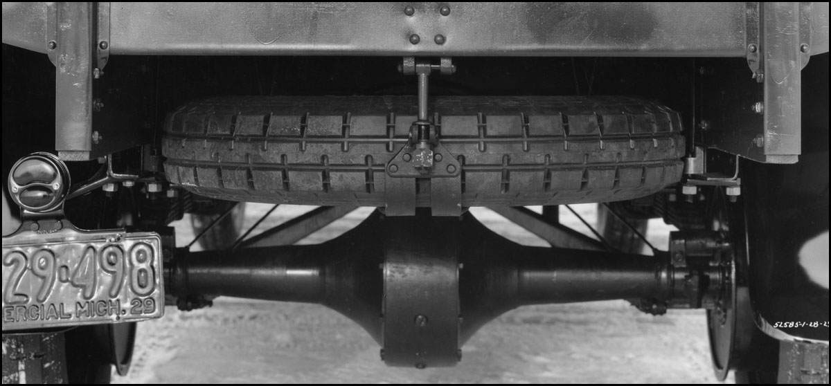
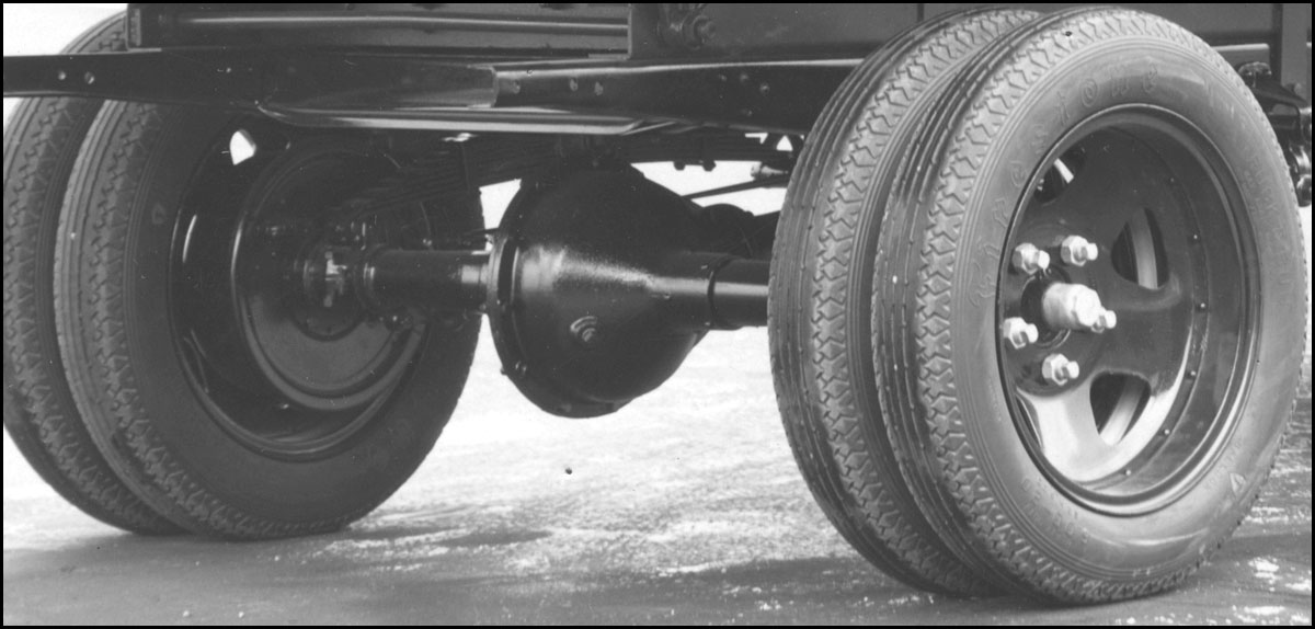
The gallery below shows an example of the three types of rear axles for identification purposes.
During the AA production time period from 1927—1932, there were nine rear axle assemblies installed on the Ford assembly lines as follows:
AA-4000-A – 1927—1929 Worm Gear 7.25:1 – AA’s without emergency brakes
AA-4000-B – 1927—1929 Worm Gear 5.17:1 – AA’s without emergency brakes
AA-4000-E – 1927—1929 Worm Gear 7.25:1 – AA’s with emergency brakes
AA-4000-F – 1927—1929 Worm Gear 5.17:1 – AA’s with emergency brakes
AA-4000-C & G – 1928—1929 Bevel Gear 7.16:1
AA-4000-D & H – 1928—1929 Bevel Gear 5.11:1
AA-4000-K – 1930—1932 Bevel Gear 6.6:1
AA-4000-L – 1930—1932 Bevel Gear 5.14:1
AA-4000-M – 1930—1932 Bevel Gear – AA112 Standrive (drop center chassis)
AA Rear Axle Type Identification Gallery
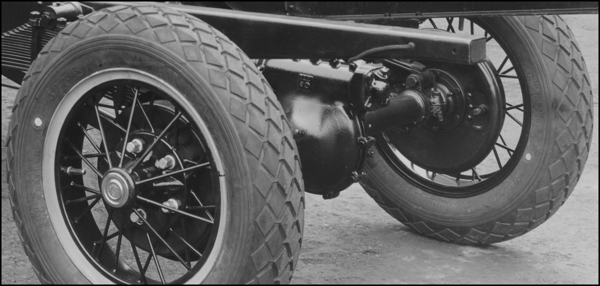
Worm Gear Axle – 1927—1929
There were two worm gear rear axle assemblies for trucks without emergency brakes (AA-4000-A with a 7.25:1 gear ratio and AA-4000-B with a 5.17:1 gear ratio).
These two assemblies looked identical externally. Internally, only the worm and worm gear were different. These two axles were used through 1928 and for some AA-chassis in early 1929.
The initial AA’s had the AA-4000-B high speed rear axle with no external identification as to the gear ratio.
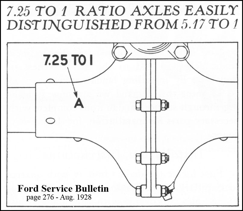
Sometime in early 1928, the low speed AA-4000-A rear axle was made available. At that time the left center section of the axle housing was stamped with an “A” for the low speed axle and a “B” for the high speed axle. Refer to the image following which identifies the stamping location.
For trucks with emergency brakes, the axle shafts and axle housings were longer (13/16″ for the axle shafts and 25/32″ for the axle housings). ?????????? is this true????????? The track (i.e. tread) was the same measurement as the prior A/B assemblies. AA-4000-E with a 7.25:1 gear ratio and AA-4000-F with a 5.17:1 gear ratio were available for the emergency brake equipped AA’s for 1929. A few late 1928 AA’s might have had emergency brakes as well.
The only difference between the E/F axle assemblies was the internal worm and worm gear. Gear ratio identification was the same “A” and “B” stamping used for rear axles without emergency brakes.
The July 24, 1929 Indianapolis service letters announced that the right hand axle housing with “HS” for high speed and “LS” for low speed axle was being used for gear ratio identification. There was no indication as to where on the right housing the stamping was located.
AA-4610-A/B Worm & Related Parts
The worm (i.e worm screw) drove the worm gear which in turn drove the rear axle shafts through the differential gears.
Watch Dave Allder’s video of an early-1928 worm gear axle below to see how this works.
Worm (or worm screw) – This part included integrated front and rear shafts. The worm was connected to the drive shaft by an internally splined coupler (part AA-4684). The coupler was installed onto the drive shaft with flat head clevis pin A-23861 (3/8″ x 2-3/32″) which was peened on both ends. The coupler was installed onto the splined shaft end of the worm with A-23860 plain pin (3/8″ x 2-12″), flat washer, and cotter. However, most installations observed have had two headless rivets peened on both ends (no pin). This makes it difficult to separate the drive shaft from the worm shaft for overhauls. The two different worms were:
AA-4610-A Worm – This was the worm for the low speed gear ratio and had four threads (i.e. four spiral teeth). It drove a 29 tooth worm gear which yielded a 7.25:1 gear ratio. Production of this worm screw and worm gear combination started in early 1928.
AA-4610-B Worm – This was the worm for the high speed gear ratio. At the start of production in 1927, part AA-4610 (with no suffix) was used. The “B” suffix was assigned when both low and high speed gear ratios were offered. This worm screw had six threads (i.e. six spiral teeth). It drove a 31 tooth worm gear which yielded a 5.17:1 gear ratio.
Roller Bearing & Sleeves – roller bearing AA-4615 and sleeve AA-4616 were installed on each end of the worm shaft. An upset on the sleeve fit into axle housing notches locked them in place. This can be seen in the video above. These were TT carry-over parts. On the front side of the front roller bearing, a retainer washer was used. Initially a TT carryover washer was used which was 1/16″ thick (part A-22437). It was replace with 1/8″ thick AA-4622 washer sometime in 1928. The back side of the rear roller bearing was held in place by a worm thrust bearing.
Worm Grease Retainer – At the front side of the front roller retainer washer there was a TT carryover grease retainer. This consisted of A-22455 felt washer followed by AA-4692 retainer cup (with the cup facing the rear and enclosing the felt washer). The cup fit into the flange at the rear of the torque tube. The felt washer and cup combination was replace with AA-4700 grease retainer assembly in late-1928 to early-1929 and is shown in image above. This assembly also fit into the flange at the rear of the torque tube.
Worm Thrust Bearing – There were several designs of the AA-4696 worm thrust bearing used during the production period.
- The image below shows the three parts which made up AA-4696 d1 worm thrust bearing. The AA-4698 ball and retainer assembly was sandwiched between two AA-4697 collars to make up the assembly. These were TT carryover parts and were used from 1927 through sometime in 1928 (possibly through October).
- A new design thrust bearing was released in late-1928 under part AA-4696-A2 (supplied by Gurney). The 10 balls of this assembly were held between outer/inner rings (i.e. races) as a permanent assembly (see the image below). This bearing was changed to a 9 ball bearing in early-1929. A 10 ball AA-4696-A3 Federal supplied bearing was used interchangeably with the 9 ball Gurney bearing starting in mid-1929. Both the 9 ball Gurney and 10 ball Federal bearings were provided through serviced as AA-4696-A2 .
- The hardware used to attach the thrust bearing to the rear shaft of the worm is shown below. The worm shaft had pin A-23767 set into the shaft to keep retainer AA-4695 from rotating. Cotter pin A-23566 was used to secure the A-21941 castle nut.
Other Parts
??????????????????????????? to be added – housings, axle shafts, spider gears, torque tube/drive shaft, radius rods
Bevel Gear Axle 1928—1929
late-1928—early-1929 – to be documented.
Bevel Gear Axle 1930—1932
1930—1932 – to be documented.
Page Contents