
2023/12/01 update
Page Contents
Speedometer Parts Overview
This article covers the AA related speedometer parts.
Note that the speedometer head and bracket assembly in the instrument panel is the same for both the A and AA and is not covered in this article. Refer to the RGJS Area 6 for these details.
Speedometer Drive and Driven Gears
There were ten different sets of drive/driven speedometer gears used during the AA production years for the three different AA rear axle types. All drive gears fit onto the drive shaft front splines. For the 1927/1928 gear set #1, the driven gear was held in a gear and cap assembly bolted to the bottom of the torque tube. All other driven gears were held in bearing AA-17269 which was screwed onto the side of the torque tube. The gear sets could not be intermixed due to the number of gear teeth and outside diameter of the drive and driven gears.
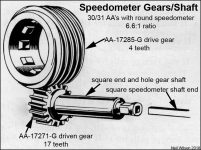
Speedometer gear sets #1 through #8 were for AA’s with the oval speedometer head (used into June 1930). Speedometer gear sets #9 and #10 were used starting June 1930 for AA’s with round Speedometer heads. The table and gallery below define speedometer drive/driven gear sets.
Note that the driven gears for the 1932-1935 axles are the same as the 1930-1931 square end shaft, driven gears.
Mobile screen horizontal avoids scrolling
| Ford Model AA’s – Speedometer Drive and Driven Gear Sets Table | ||||||||||
|---|---|---|---|---|---|---|---|---|---|---|
| Axle | Speedometer Drive and Driven Gear | |||||||||
| Type | Ratio | Set | Part | Type | Stamping | Teeth | OD | Length | Type | Year |
| Neil Wilson 2018 | ||||||||||
| 1928 & 1929 Worm and Bevel Gear Axles | ||||||||||
| Worm | 5.17 | 1 | AA 17285 | Drive | no stamping | 5 | 1.851/1.854 | 1.09 | 27 28 | |
| AA 17271-B | Driven | 15 | 0.85 | 2.415 | slotted | |||||
| Worm | 5.17 | 2 | AA 17285-B | Drive | 5 1/6-1 32×6 also 5.17 | 6 | 1.715 | 1.09 | 28 | |
| AA 17271-D | Driven | 5 1/6-1 32×6 also 32×6 | 19 | 1.35 | slotted | |||||
| Worm | 7.25 | 3 | AA 17285-C? | Drive | no example | ? | ? | ? | 28 | |
| AA 17271-C? | Driven | 7-25 | 18 | 1.005 | slotted | |||||
| bevel | 5.11 | 4 | AA 17285-? | Drive | no example | ? | ? | ? | 29 | |
| AA 17271-? | Driven | 5.11 30×5 | 19 | 1.15 | slotted | |||||
| both | 5.11 or 5.17 | 5 | AA 17285-D | Drive | 5.11 or 5.17 | 6 | 1.713/1.715 | 1.09 | 29 | |
| AA 17271-D | Driven | 19 | 1.036/1.039 | slotted | ||||||
| both | 7.17 or 7.25 | 6 | AA 17285-E | Drive | 7.17 or 7.25 | 4 | 1.744/1.746 | 1.09 | 29 | |
| AA 17271-E | Driven | 18 | 1.005/1.008 | slotted | ||||||
| 1930 & 1931 Bevel Gear Axle | ||||||||||
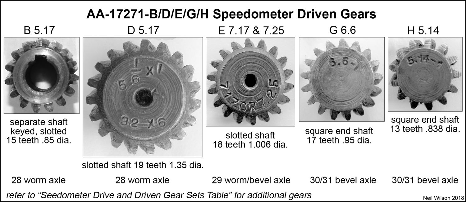
| bevel | 5.14 | 7 | AA 17285-F | Drive | no example | 6 | ? | ? | 30 | |
| AA 17271-D | Driven | 5.14-1 | 19 | 1.036 | slotted | |||||
| bevel | 6.6 | 8 | AA 17285-G | Drive | 6.6-1 | 4 | 1.795 | 0.905 | 30 | |
| AA 17271-F | Driven | 17 | 0.955 | slotted | ||||||
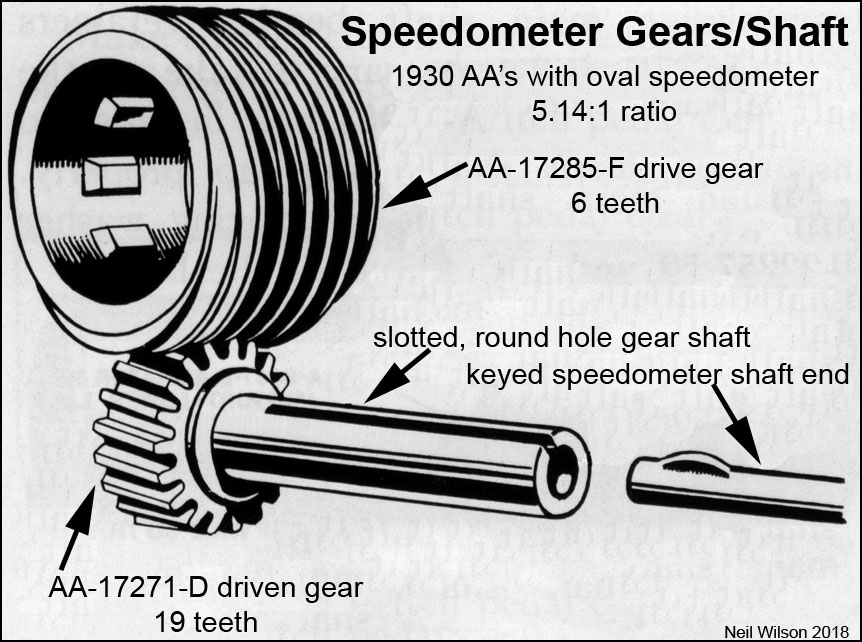
| bevel | 5.14 | 9 | AA 17285-H | Drive | AA 17285-H 5.14-1 | 4 | 1.935 | 0.905 | 30 31 | |
| AA 17271-H | Driven | 5.14-1 | 13 | 0.838 | square | |||||
| bevel | 6.6 | 10 | AA 17285-G | Drive | 6.6-1 | 4 | 1.795 | 0.905 | 30 31 | |
| AA 17271-G | Driven | 17 | 0.953 | square | ||||||
Note for Webmaster – table created from D:\websites\aafords\d.aafords-tbl > tbl-cha-html.xlsx
-
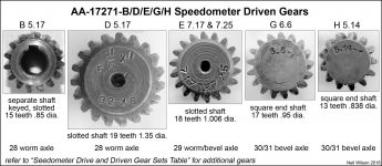
- AA-17271-B,D,E,G,H Speedometer Driven Gears
-

- Speedometer Gears/Shaft – Set #7 – 1930
-

- Speedometer Gears/Shaft – Set #9 – 1930-1931
-
- Speedometer Gears/Shaft – Set #10 – 1930-1931

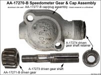
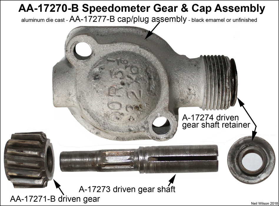
Speedometer Gear and Cap Assembly (1927 – early 1928)
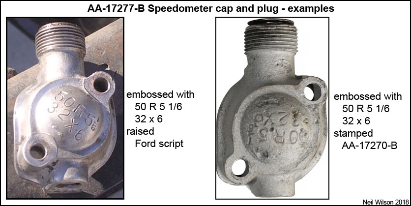
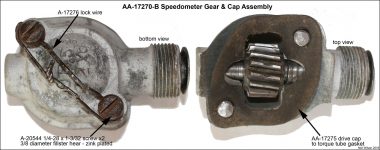
The first AA’s used AA-17270-B speedometer gear and cap assembly which was designed like the A chassis corresponding assembly. The AA assembly included AA-17277-B cap/plug assembly, AA-17271-B driven gear, A-17273 driven gear shaft, and A-17274 driven gear shaft retainer.
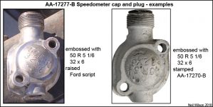
The cap was embossed with “50R 5 1/6 32 x 6”. Of the two caps observed one had a small, raised Ford script and the other was stamped with AA-17271-B (both below the 32 x 6).
The AA torque tube was designed for attaching the assembly to the bottom of the tube with two zinc plated A-20544 1/4–28 x 1-3/32 fillister head screws (heads were 3/8 diameter and cross drilled for lock wire A-17276). Also, like the A chassis, there was a cap to torque tube gasket – part AA-17275.
-
- AA-17270-B Speedometer Gear and Cap Assembly
-
- AA-17277-B Speedometer Cap and Plug Assembly – examples
-
- AA-17270-B Speedometer Gear and Cap Assembly – views

-
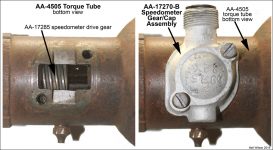
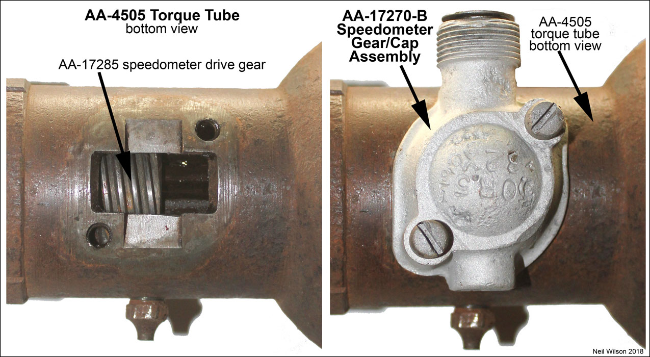
- AA-4505 Torque Tube views at Speedometer Gear & Cap assembly AA-17270-B
Speedometer Driven Gear Bearing
In early 1928 a new group of parts was put into production which replaced the short-lived speedometer gear and cap assembly (AA-17270-B). The new parts were:
- Speedometer gear set #2 – AA-17285-B Speedometer Drive Gear and AA-17271-D Speedometer Driven Gear (with integral slotted gear shaft)
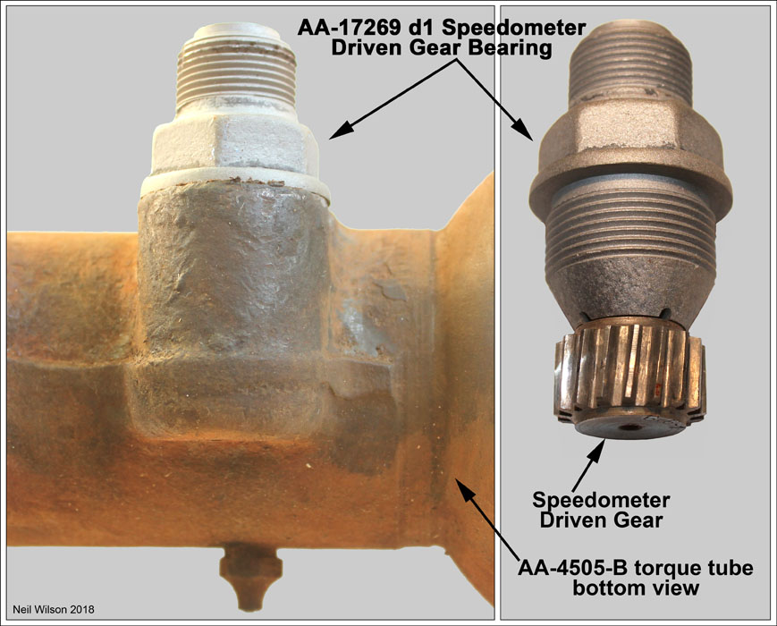
- Speedometer Driven Gear Bearing AA-17269 (which screwed into the torque tube)
- Torque Tube AA-4505-B (with threaded side opening for the new speedometer bearing)
With subsequent Ford design changes, this new setup was used for the remainder of AA production. Speedometer gear sets #3 through #10 were the major changes to this setup. Also, new torque tubes were added to the mix for the 1929 and 1930/1931 bevel gear axles.
The new AA-17269 bearing was designed to screw into the torque tube. This bearing held the new driven gear. With the bearing installation the driven gear teeth meshing with the teeth of the driving gear. The rear of the speedometer casing/shaft assembly was attached to the bearing and the shaft of the driven gear. There were two bushing designs:
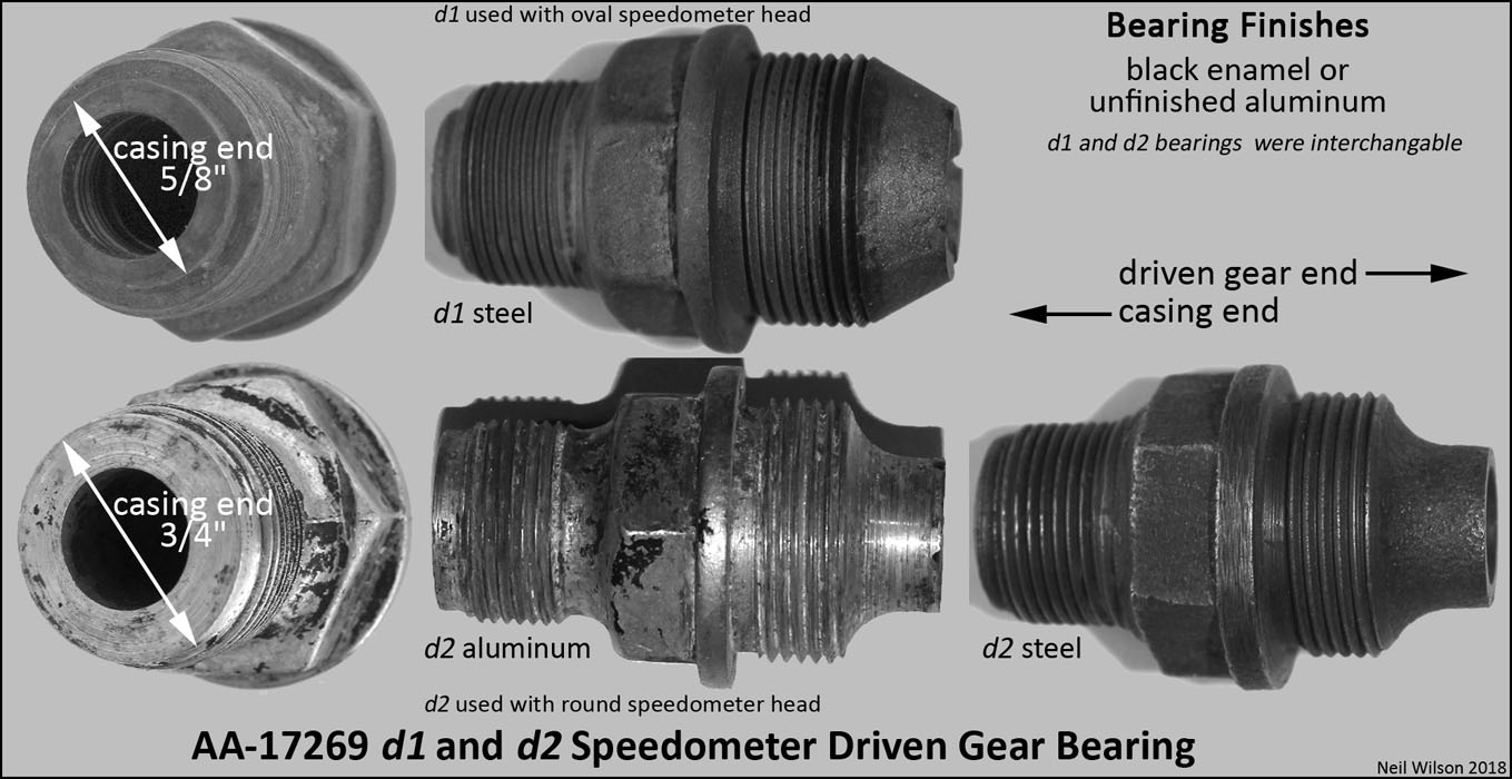
- AA-17269 d1 bearing was made of steel and had a 5/8” diameter outer end to accommodate the oval speedometer’s AA-17260 shaft/casing assembly.
- AA-17269 d2 bearing started production with the round speedometer’s AA-17260-C/D shaft/casing assemblies. This bearing was either aluminum or steel and had a 3/4” outer end diameter to accommodate the larger sized end flange on the new shaft/casing assembly.
Both styles of bearings were interchangeable. The bearing finish was black enamel or unfinished aluminum.
Speedometer Gear Bearing Gallery
-

- AA-4505-B Torque Tube with AA-17269 Bearing Installed
-
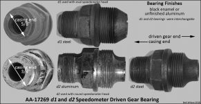
- AA-17269 d1 and d2 Speedometer Driven Gear Bearing
Speedometer Drive Gear Retainers and Thrust Washer
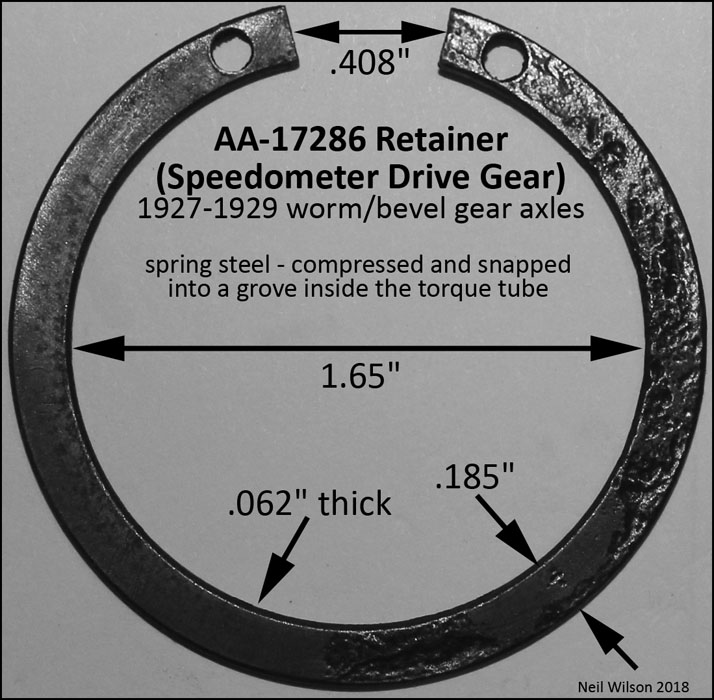
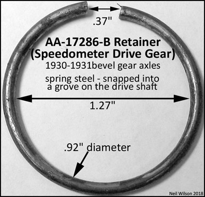
For the 1928 and 1929 rear axles, the speedometer drive gear was slid onto the drive shaft after the drive shaft roller bearing. Then, spring steel, speedometer drive gear retainer AA-17286 was inserted into a grove in the torque tube.
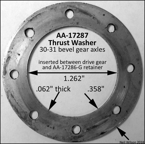
For the 1930 and 1931 rear axle, the speedometer drive gear was slid onto the drive after the shaft roller bearing. Then, thrust washer AA-17287 was placed onto the drive shaft. This was followed by AA-17286-B speedometer drive gear retainer. This spring steel retainer was slid into a grove in the drive shaft.
Speedometer Retainers/Thrust-Washer Gallery
-

- AA-17286 Retainer (Speedometer Drive Gear)
-

- AA-17287 Thrust Washer (Speedometer Drive Gear)
-

- AA-17286-B Retainer (Speedometer Drive Gear)
Speedometer Shaft/Casing Assemblies
The AA chassis speedometer shaft and casing assemblies were longer versions of the assemblies used for the A chassis. There were two basic designs – one for the oval speedometer head and one for the round speedometer head. The casing finish was raven as per the RGJS Area 1 (referred to as “cable”).
Note that the 1928 through 1929 Ford Parts Price Lists uses the term “Cable” rather than “Casing”. The Ford engineering drawings started using “Casing” in January 1928. This article uses the term “Casing” for consistency.
Note that vendor catalogs use various terms for these assemblies (different per vendor). The detail descriptions needs to be checked and a phone call for verification is best. These are aftermarket assemblies and only similar to original assemblies.
Oval Speedometer Shaft/Casing Assembly
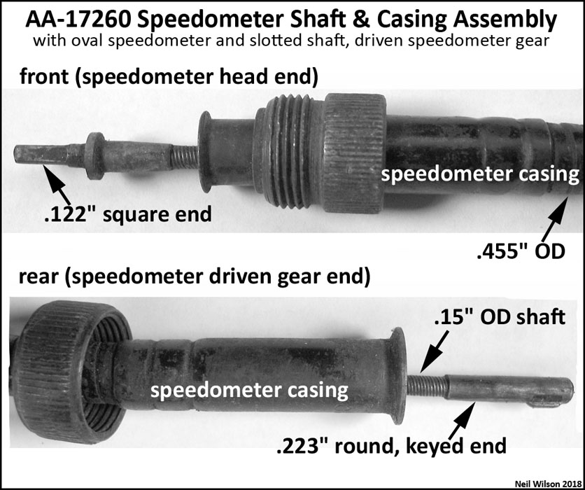
AA-17260 Speedometer Shaft/Casing Assembly
AA-17260 speedometer shaft/casing assembly was for AA’s with an oval speedometer. This assembly includes a .455″ (about 29/64″) OD casing and a .15″ OD shaft. The front of the shaft was a .122″ square which fit the oval speedometer head. The rear of the shaft had a round, keyed end which fit the slotted shaft of the speedometer driven gear. All AA’s with oval speedometer heads used speedometer driven gears with a slotted shaft.
There were many different lengths of these assemblies. Of nine original casings measured, none were the same length. Lengths ranged from 80″ to 82-1/2″. Lengths were likely changed due to different routing paths made through December 1929. Through service, the AA-17260 assembly would have been ordered rather than ordering just individual part. Otherwise, a miss-match in casing and shaft lengths would have likely resulted.
Refer to Shaft Test/Replacement below.
Round Speedometer Shaft/Casing Assemblies

AA-17260C/D Speedometer Shaft/Casing Assemblies
These assemblies were for AA’s with a round speedometer. AA-17260-C was for the AA131 and AA-17260-D was for the AA157. Engineering drawings for the AA112 have not been found. This chassis likely used the AA131 assembly (AA-17260-C) or had an assembly with a unique length.
The AA-17260-C/D speedometer shaft/casing assemblies includes a .32″ (about 29/64″) OD casing and a .11″ OD shaft. The front end of the shaft was a .102″ square which fit the oval speedometer head. The rear end of the shaft had a .102″ square end which fit the speedometer driven gear. All AA’s with an oval speedometer head uses a speedometer driven gear with a square hole in the outer end.
These C and D assemblies are not listed in the Ford Parts Price List booklets. The shaft and casing are listed as separate service replacement parts. Lengths shown below are from the 1940 Ford Chassis Parts Catalog:
- AA-17262-C speedometer shaft (AA131 and possibly AA112) – 82″
- AA-17261-C speedometer casing (AA131 and possible AA112) – 81.5″
- AA-17262-D speedometer shaft (AA157) – 111″
- AA-17261-D speedometer casing (AA157) – 110.5″
Two of the AA-17261-C casings from AA131 trucks were checked for length. They were 81-1/4” and 81-7/8” long. So, it must be that the casing length was changed over time without new part numbers being assigned. This would indicate that the parts were backward compatible. However, if only one part had been ordered for service, a miss-match of lengths was possible.
Refer to Shaft Test/Replacement below.
Speedometer Shaft Test/Replacement
Speedometer Shaft Length-Testing
To test that a shaft is the correct length for an original casing, the assembly can be connected to a correct oval or round speedometer head and the driven gear bearing. The driven gear can then be inserted into the bearing so that the gear’s integral shaft fits onto speedometer shaft’s rear fitting. If the driven gear does not rest against the end of the bearing, then the shaft is too long. If turning the driven gear does not engage the speedometer, then the speedometer shaft is too short (i.e. it is not inserting into the driven gear’s shaft).
Speedometer Shaft Replacement
To replace a speedometer shaft for an original AA speedometer casing, the shaft can to be made by a shop which specializes in this service. The shop will need the speedometer head, casing, speedometer driven gear bearing, and speedometer driven gear. This also allows for a shaft to be made for a miss-match of speedometer head and speedometer driven gear (example – an oval speedometer and a square ended speedometer driven gear which would have been for a round speedometer).
Speedometer Casing Supports and Clips
Casing Clip on-dash
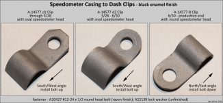
Clip A-14577 d1 and d2 were used to hold the speedometer casing to the right-inside of the dash. These clips were used with the oval speedometer head. The in-dash D-nut for clip installation was a 2-1/2″ above and in-line with the choke rod in-dash hole. The clip was installed with the bolt upwards and the clip at a South/West angle. See the gallery below for more details.
Clip A-14577-B replaced the d2 clip in June 1930 for AA’s with the round speedometer head. The in-dash D-nut for clip installation was 3-1/2″ above and 3-5/8″ left of the choke rod in-dash hole. The clip was installed with the bolt downwards and the clip at a North/East angle. See the gallery below for more details.
Clips were black enamel finished and installed with A-20427 #12-24 x 1/2 round head bolt (raven finish) and A-22139 unfinished lock washer.
Note that clip A-14577 d1 and d2 were also used to secure the on-water-inlet terminal box to generator conduit through-out production. In June 1930 the part id was given a “A” suffix.
Casing Supports on-frame
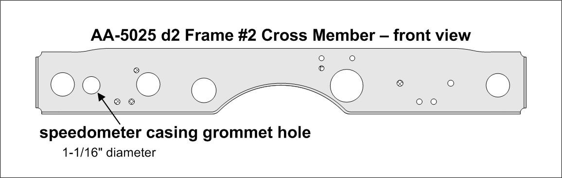
There were two different on-frame casing supports used on the AA chassis with the AA-5025 d1 #2 frame cross member. This cross member was used into until early 1929 and was an inverted “U” design (all most identical to the A chassis). Starting in early 1929 the flat/flanged, AA-5025 d2 #2 frame cross member was used. It had a speedometer casing grommet hole. So, a grommet was use and the casing support was eliminated.
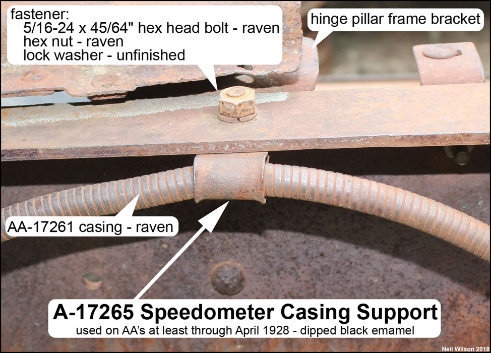
Casing Support on-frame #1
The first on-frame support was A-17265. It was used for both the A and AA chassis. It can be seen in the gallery below. For the AA chassis, this support was used at least through April 1928. From the support, the casing was routed under the service brake cross shaft and then through a grommet in the frame #3 cross member.
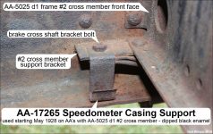
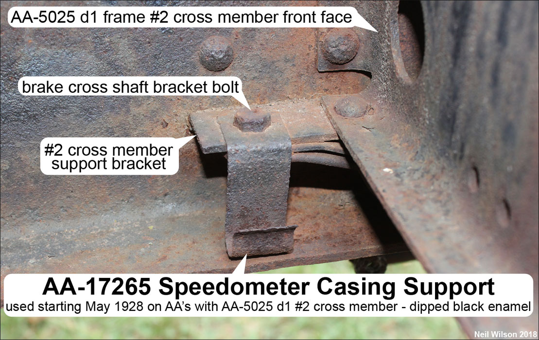
Casing Support on-frame #2
The second on-frame support was AA-17265. It can be seen in the gallery below. This support was installed on the right side under the head of the forward bolt attaching the brake cross shaft to frame bracket. The location of this support resulted in moved the casing down from the top of the frame to below the brake cross shaft. This support was used starting mid -928 and into early 1929 with the AA-5025 d1 #2 frame cross member. From the support, the casing was routed through a grommet in the frame #3 cross member.
Casing Clip on-frame
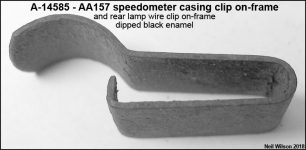
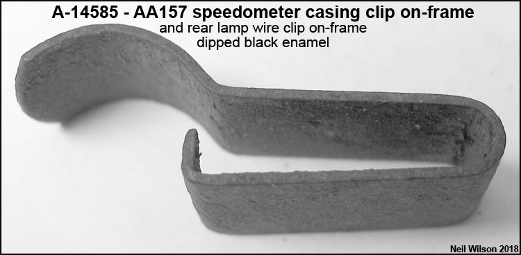
Given the additional AA157 chassis length between frame cross member #2 and #3, clip A-14585 was used to secure the speedometer case between these two frame cross members. The clip was centrally located on the inside, bottom of the right-hand side frame member. The AA section of the December 20, 1932 Ford Parts Price List has A-14585 described as “Speedometer cable clip – on frame – 157”. See the gallery below.
Note – A-14585 was the “Rear lamp wire clip on frame” as well.
Speedometer Clips/Supports Gallery
-
- A-14577 and A-14577-B Speedometer Casing to Dash Clips

-

- A-17265 Speedometer Casing Support
-
- AA-17265 Speedometer Casing Support
-
- A-14585 Speedometer Casing Clip – AA157
Speedometer Casing Grommets
Note – All speedometer casing grommets were a split design. Vendor sold grommets are not split and therefore need to be cut for originality and installation.
Casing Grommet in-gas-tank-assembly
A-9066 gas tank speedometer casing support grommet was used for both the A and AA chassis with the oval speedometer head. This split grommet was located in the bottom section of the gas tank wiring/casing tunnel. See gallery below.
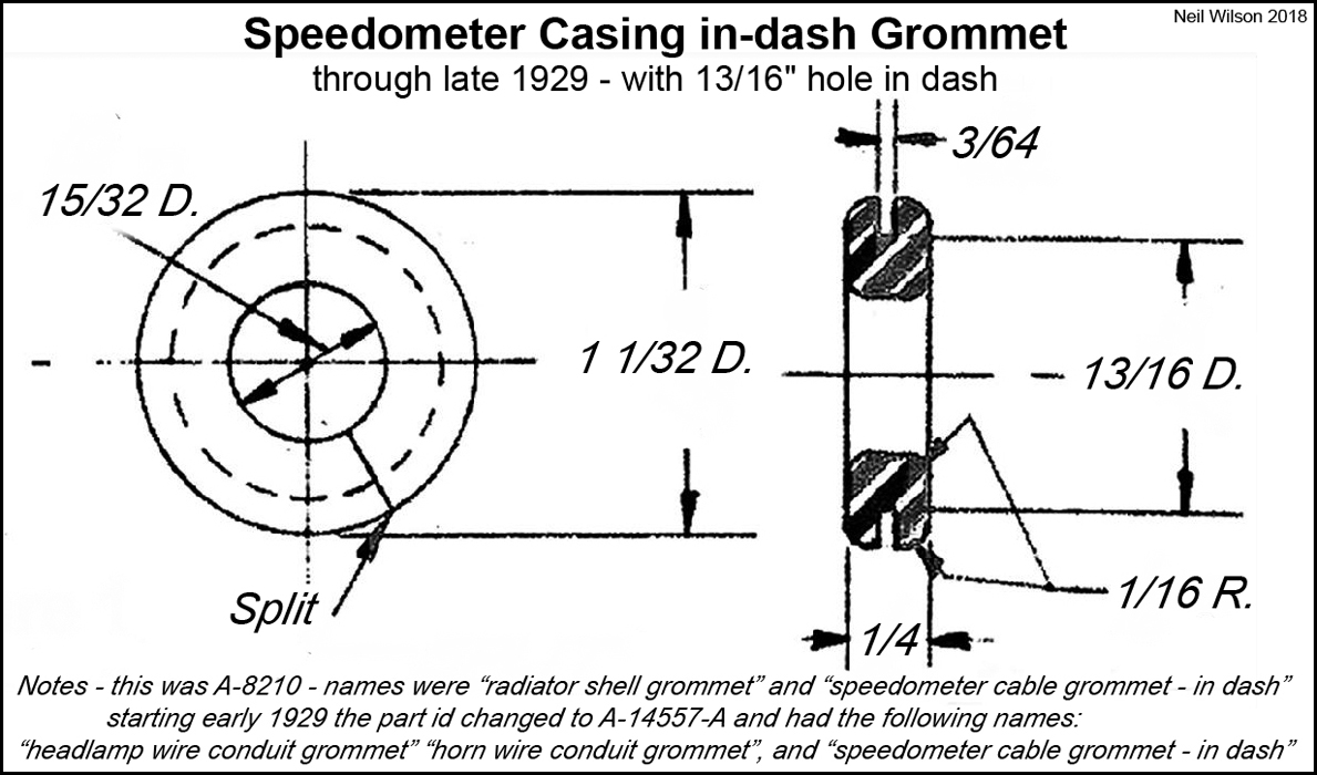
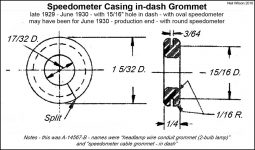
Casing Grommet in-dash
This split type grommet was used for the both the A and AA chassis. Initially the hole in the dash for this grommet was 13/16″. The hole was located to the right of the choke rod hole. At production start, the grommet was A-8210 “speedometer casing in-dash grommet”. The part id was changed to A-14567-A (most likely in early 1929). In the later part of 1929 the hole in the dash was increased to 15/16″ diameter and grommet A-14567-B was used for the oval speedometer head casing through June 1930. No additional grommet is shown in the Parts Price Lists or engineering drawing list. Consequently, it is assumed that grommet A-14567-B was also used for the smaller 19/64″ diameter, round speedometer head casing (June 1930 – production end). See the gallery below for drawings of these two grommets.
Casing Grommets in-frame
Initially, the speedometer casing was routed under the service brake cross shaft and through AA-17265 grommet in the #3 frame cross member. The location of the grommet hole for this split grommet is shown in the gallery below.
The size of the #3 cross member grommet hole was enlarged sometime in 1928. A new AA-17266 grommet was released. AA-17266 Ford engineering drawing is dated 6/4/28 and this part shows up in the Oct. 1928 Ford Parts Price List.
Grommet AA-17266 was also used starting in early 1929 with all versions of the AA-5025 d2 #2 frame cross member (see gallery below). This d2 cross member included a grommet hole for routing the speedometer casing above the service brake cross shaft.
Speedometer Casing Grommets Gallery
-
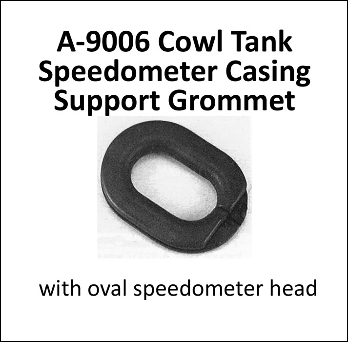
- A-9006 Cowl Tank Speedometer Casing Support Grommet
-
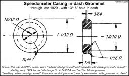
- A-8210 Speedometer in-dash Grommet
-
- A-14567-B Speedometer in-dash Grommet

-
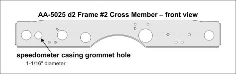
- Speedometer Grommet Hole – AA-5025 Frame #2 Cross Member
-
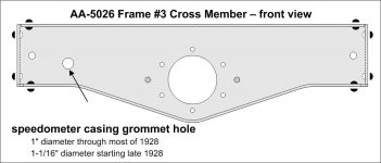
- Speedometer Grommet Hole – AA-5026 Frame #3 Cross Member

Page Contents